
Augmented reality display comprising eyepiece having a transparent emissive display

a technology of augmented reality and eyepieces, applied in the field of display systems, to achieve the effect of reducing the refraction

Pending Publication Date: 2019-04-11
MAGIC LEAP
View PDF4 Cites 23 Cited by
  • Summary
  • Abstract
  • Description
  • Claims
  • Application Information

AI Technical Summary

Benefits of technology

The patent describes head mounted display systems with eyepices that display augmented reality image content to a user's vision field. The eyepice is made of a frame and an emissive display that is transparent and emits light to the user's eye. The emissive display has a plurality of emitters that are arranged in a matrix to display augmented reality image content. The system may also include a proximal lens array or a distal lens array to reduce divergence of the light emitted from the display and to collimate or vary the focus of the light. The system may also include a proximal or distal variable focus optical element to alter the view of the environment in front of the user. The patent also describes the use of occluders to create a more immersive experience for the user. The technical effects of the patent include improved augmented reality image content display and reduced eye strain for users wearing the head mounted display system.

Problems solved by technology

Because the human visual perception system is complex, it is challenging to produce an AR technology that facilitates a comfortable, natural-feeling, rich presentation of virtual image elements amongst other virtual or real-world imagery elements.

Method used


Image

  • Augmented reality display comprising eyepiece having a transparent emissive display
  • Augmented reality display comprising eyepiece having a transparent emissive display
  • Augmented reality display comprising eyepiece having a transparent emissive display

Examples


Embodiment Construction

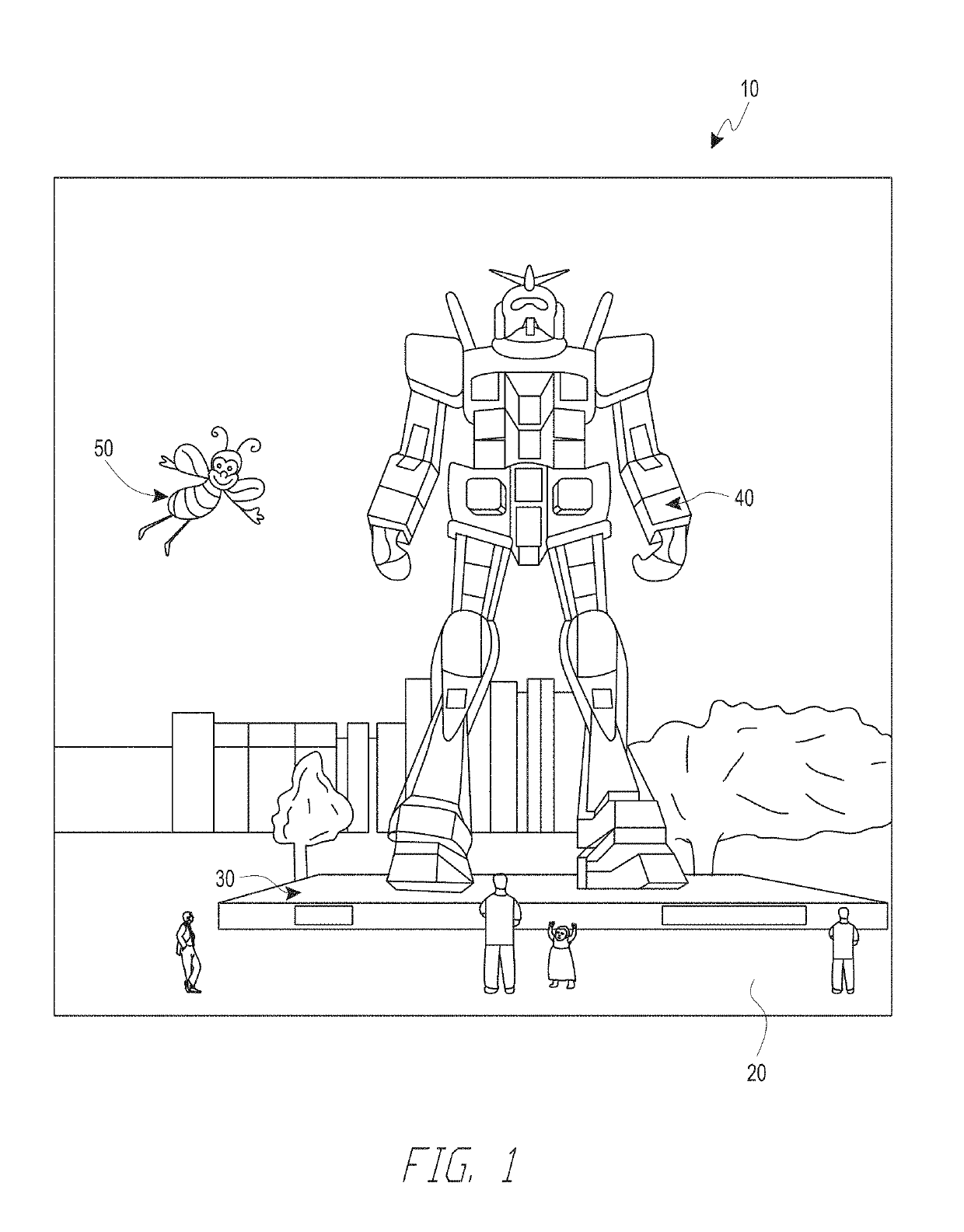
[0194]Reference will now be made to the drawings, in which like reference numerals refer to like parts throughout. Unless indicated otherwise, the drawings are schematic not necessarily drawn to scale.

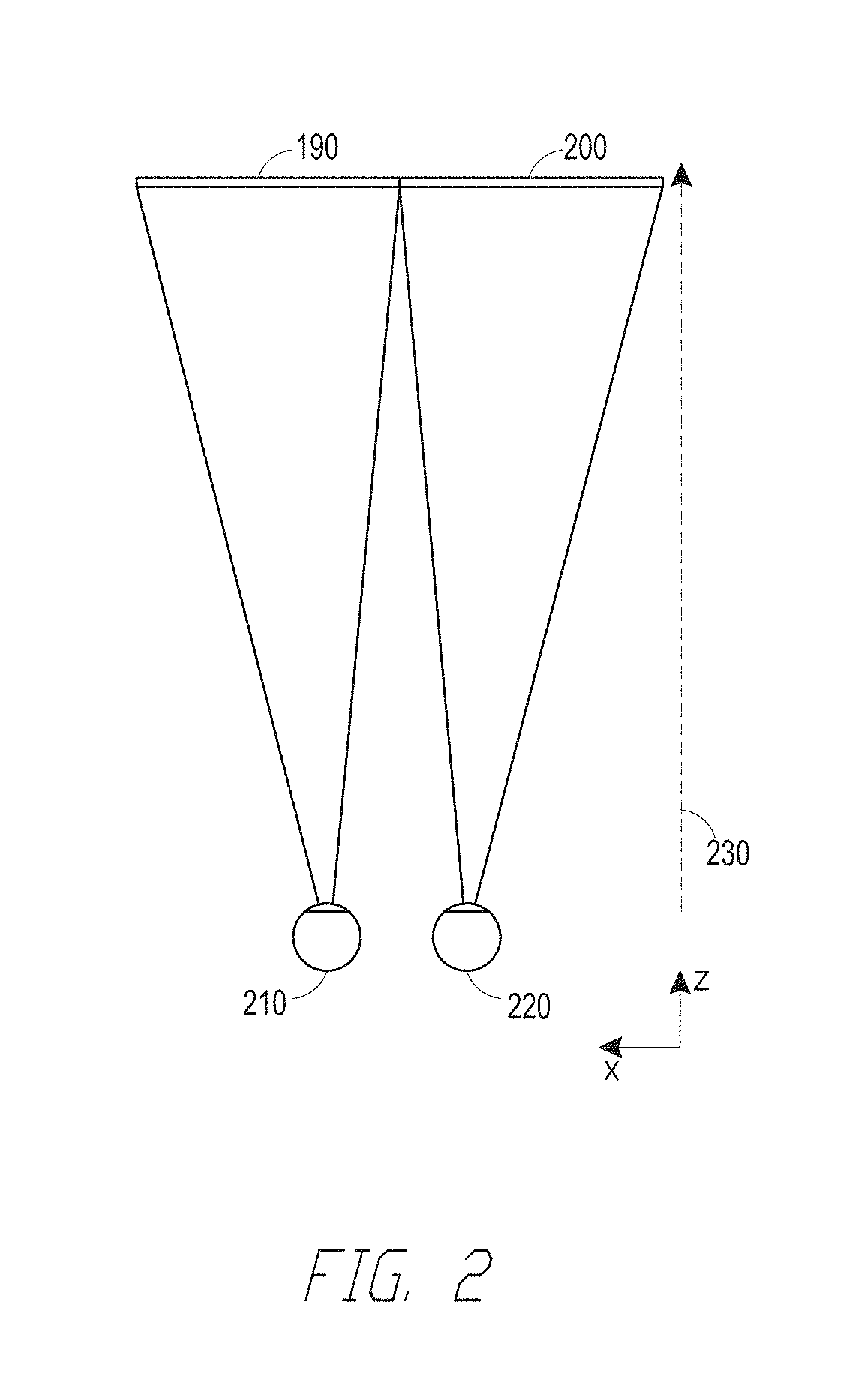
[0195]FIG. 2 illustrates a conventional display system for simulating three-dimensional imagery for a user. It will be appreciated that a user's eyes are spaced apart and that, when looking at a real object in space, each eye will have a slightly different view of the object and may form an image of the object at different locations on the retina of each eye. This may be referred to as binocular disparity and may be utilized by the human visual system to provide a perception of depth. Conventional display systems simulate binocular disparity by presenting two distinct images 190, 200 with slightly different views of the same virtual object—one for each eye 210, 220—corresponding to the views of the virtual object that would be seen by each eye were the virtual object a real object at a...


PUM


Abstract

An augmented reality head mounted display system an eyepiece having a transparent emissive display. The eyepiece and transparent emissive display are positioned in an optical path of a user's eye in order to transmit light into the user's eye to form images. Due to the transparent nature of the display, the user can see an outside environment through the transparent emissive display. The transmissive emissive display comprising a plurality of emitters configured to emit light into the eye of the user. A first variable focus optical element is positioned between the transparent emissive display and the user's eye and is configured to modify emitted light to provide the appropriate amount of divergence for image information to be interpreted by the user as being on a particular depth plane. A second variable focus optical element is positioned between the transparent emissive display and the environment and is configured to offset effects of the first variable focus optical element on the view of the environment.

Description

CROSS-REFERENCE TO RELATED APPLICATIONS[0001]This application claims the benefit of priority under 35 U.S.C. § 119(e) to U.S. Provisional Patent Application No. 62 / 571,203 filed Oct. 11, 2017, entitled “AUGMENTED REALITY DISPLAY COMPRISING EYEPIECE HAVING A TRANSPARENT EMISSIVE DISPLAY”, the disclosure of which is hereby incorporated by reference herein in its entirety.INCORPORATION BY REFERENCE[0002]This application incorporates by reference the entirety of each of the following patent applications: U.S. application Ser. No. 14 / 555,585 filed on Nov. 27, 2014, published on Jul. 23, 2015 as U.S. Publication No. 2015 / 0205126; U.S. application Ser. No. 14 / 690,401 filed on Apr. 18, 2015, published on Oct. 22, 2015 as U.S. Publication No. 2015 / 0302652; U.S. application Ser. No. 14 / 212,961 filed on Mar. 14, 2014, now U.S. Pat. No. 9,417,452 issued on Aug. 16, 2016; U.S. application Ser. No. 14 / 331,218 filed on Jul. 14, 2014, published on Oct. 29, 2015 as U.S. Publication No. 2015 / 0309263;...

Claims


Application Information

Patent Timeline
IPC IPC(8): G02B27/01G09G3/3208
CPCG02B27/0172G09G3/3208G09G2340/12G06T19/006G02B2027/0178G09G3/003G09G2340/10G02B2027/0185G02B3/0006
Inventor EDWIN, LIONEL ERNESTYEOH, IVAN LI CHUEN
Owner MAGIC LEAP
Learn More