
Multi-stage multiphase mixture pump visualization device and method with an undisturbed inlet

A non-disturbance, inlet technology, applied in the components of pumping devices for elastic fluids, radial flow pumps, pumps for special fluids, etc., can solve the problem of lack of qualitative and quantitative transient effects, and achieve easy and frequent disassembly and assembly. Replaceable, reproducible, reduces flow resistance and turbulence

Pending Publication Date: 2021-05-07
XI AN JIAOTONG UNIV
View PDF0 Cites 0 Cited by
  • Summary
  • Abstract
  • Description
  • Claims
  • Application Information

AI Technical Summary

Problems solved by technology

There is a lack of qualitative and quantitative understanding of the transient effects of flow patterns such as uniform bubbly flow and intermittent flow on the two-phase pressurization characteristics in actual pipes
There is no official report on the research on the undisturbed gas-liquid flow at the inlet of the mixed pump and related technologies

Method used


Image

  • Multi-stage multiphase mixture pump visualization device and method with an undisturbed inlet
  • Multi-stage multiphase mixture pump visualization device and method with an undisturbed inlet
  • Multi-stage multiphase mixture pump visualization device and method with an undisturbed inlet

Examples


Embodiment 1

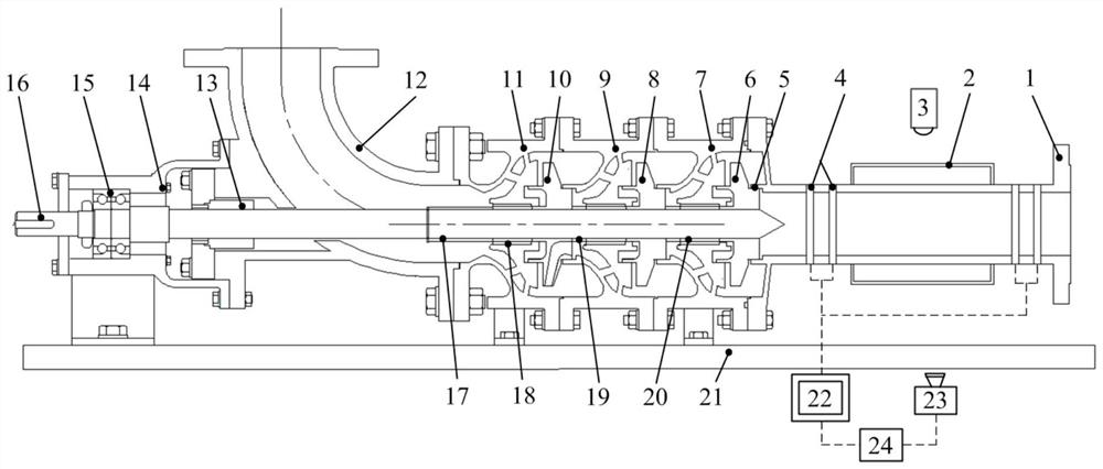
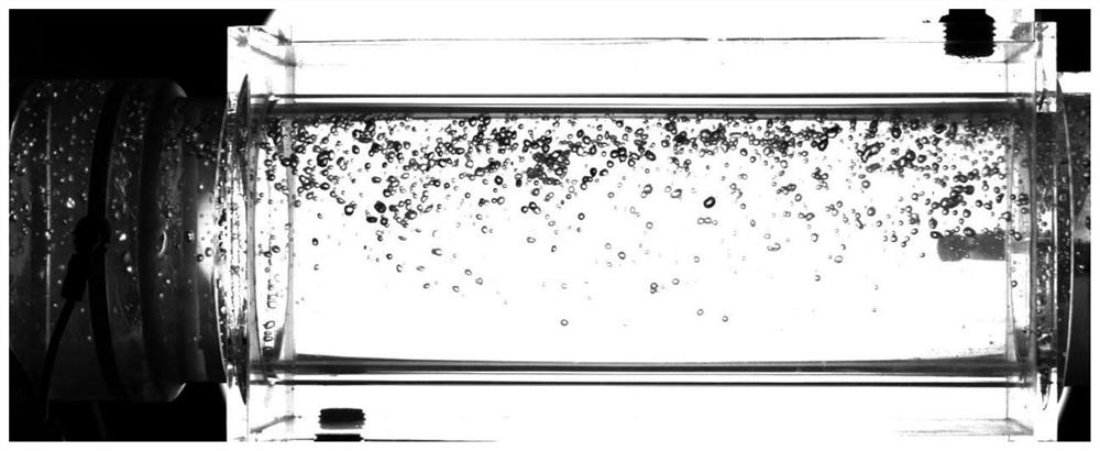
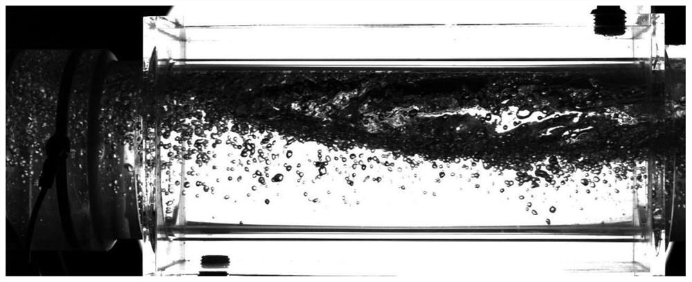
[0029] Example 1: Visual capture of inlet bubbly flow and slug flow interface

[0030] This embodiment will describe the visual capture method of phase interface characteristics of different inlet gas-liquid flow patterns, and describe the method in detail. The specific implementation is as follows:

Embodiment 2

[0033] Example 2: Dynamic change of liquid holdup at the inlet of bubbly flow and slug flow

[0034] In the above example, the method for obtaining the gas-liquid phase distribution parameters of different flow patterns is given and the distribution of the phase interface is described. In this example, the inlet phase parameters of the multi-stage multi-phase mixed pump under different flow patterns are obtained by using a conductivity probe. Transient change characteristics, the specific implementation is as follows:

[0035] Example conditions: the water flow rate at the inlet of the multi-stage multi-phase mixed pump is 25m 3 / h, the volumetric gas fractions are 5.1% and 20.6%, respectively, the rotational speed is 3500rpm, and the visualized inlet pressure is 0.25MPa. First, connect two pairs of double-ring probes arranged on both sides of the optical path compensation water jacket to the processing and acquisition module, and connect the synchronizer. The inlet and outle...

Embodiment 3

[0037] Example 3: Pressure change along the flow direction of a multi-stage mixed transport pump under a bubble-like flow inlet

[0038] The proposed multi-stage multi-phase mixed pump is connected by interstage flanges, which is easy to disassemble, and it is also convenient to arrange pressure measuring points to obtain pressure characteristics at different positions along the flow direction. The conditions of the example above were adopted.

[0039] Example conditions: the water flow rate at the inlet of the multi-stage multi-phase mixed pump is 25m 3 / h, the volumetric gas fraction is 5.1%, the rotational speed is 3500rpm, and the visualized inlet pressure is 0.25MPa. The pressure measuring points are arranged between the stages of the multi-stage multi-phase mixed pump, and the measuring points are respectively: the inlet of the mixed pump, the inlet of the impeller, the outlet of the diffuser, the cavity and the outlet of the mixed pump, etc. Among them, the inlet of t...


PUM


Abstract

The invention discloses a multi-stage multiphase mixture pump visualization device and method with an undisturbed inlet. The device and the method can realize undisturbed visual observation and measurement of gas-liquid flow patterns and phase parameters at the inlet of a mixture pump. The device is specifically characterized in that the device adopts the structural arrangement of an axial inlet and a radial outlet, the pipe diameter of an inlet visible section is the same as that of an impeller inlet, and continuous flow and no disturbance are guaranteed. A light path compensation water jacket is additionally arranged to reduce the influence of light path refraction of a pipe wall. A double-ring conducting probe is arranged in a visible section, so that the real-time change of the phase volume fraction can be reflected. Each stage of the multi-stage pump is formed by connecting an impeller and a diffuser in series, and the stages are connected through flanges so as to facilitate disassembling. A light source and a high-speed camera are oppositely arranged, and inlet gas-liquid flow images are visually and accurately obtained. According to the multi-stage multiphase mixture pump visualization device and method, undisturbed visualization observation and phase parameter measurement of inlet flow of the mixture pump can be effectively achieved, all connecting parts can adapt to frequent disassembly, assembly and replacement, and application is quite flexible.

Description

technical field [0001] The invention belongs to the technical field of fluid machinery and petroleum engineering multiphase flow intersecting, in particular to a device and method for visualizing the flow of a multiphase mixed pump in the process of mixed transportation and pressurization, and in particular to a multi-stage multiphase mixed transportation without disturbance at the inlet Pump visualization device and method. Background technique [0002] As the exploitation of oil and gas resources gradually proceeds to the deep sea, the water depth gradually increases, and the length of the pipeline gradually increases, resulting in a significant increase in the flow resistance of multiphase fluids in the mixed transportation pipeline, resulting in a decrease in oil and gas production. In order to effectively increase the output of oil and gas recovery and transportation, multiphase mixed transportation pumps are often installed on the mixed transportation pipeline to simul...

Claims


Application Information

Patent Timeline
Patent Type & Authority Applications(China)
IPC IPC(8): F04D1/06F04D7/04F04D29/42F04D29/44F04D15/00F04D29/08H04N5/232H04N5/235H04N5/76
CPCF04D1/06F04D7/04F04D29/426F04D29/4273F04D29/4293F04D29/445F04D15/0088F04D29/086H04N5/76H04N23/67H04N23/74H04N23/695
Inventor 郭烈锦常亮杨晨宇徐强苏筱斌张雪梅
Owner XI AN JIAOTONG UNIV
Learn More