
Program generating apparatus and program generating method

Active Publication Date: 2019-04-11
FANUC LTD
View PDF3 Cites 0 Cited by
  • Summary
  • Abstract
  • Description
  • Claims
  • Application Information

AI Technical Summary

Benefits of technology

The present invention aims to provide a program generating apparatus and method that can reduce the number of times the operator performs core removal process during machining with a wire electrical discharge machine. This results in a program that can efficiently reduce the operator's workload.

Problems solved by technology

When a machining process on a workpiece involves both the fixing process and the uncut process, problems tend to occur that the operator has to perform removal of cores an increased number of times, depending on the order the cores are machined.

Method used


Image

  • Program generating apparatus and program generating method
  • Program generating apparatus and program generating method
  • Program generating apparatus and program generating method

Examples


first embodiment

[Configuration of Program Generating Apparatus]

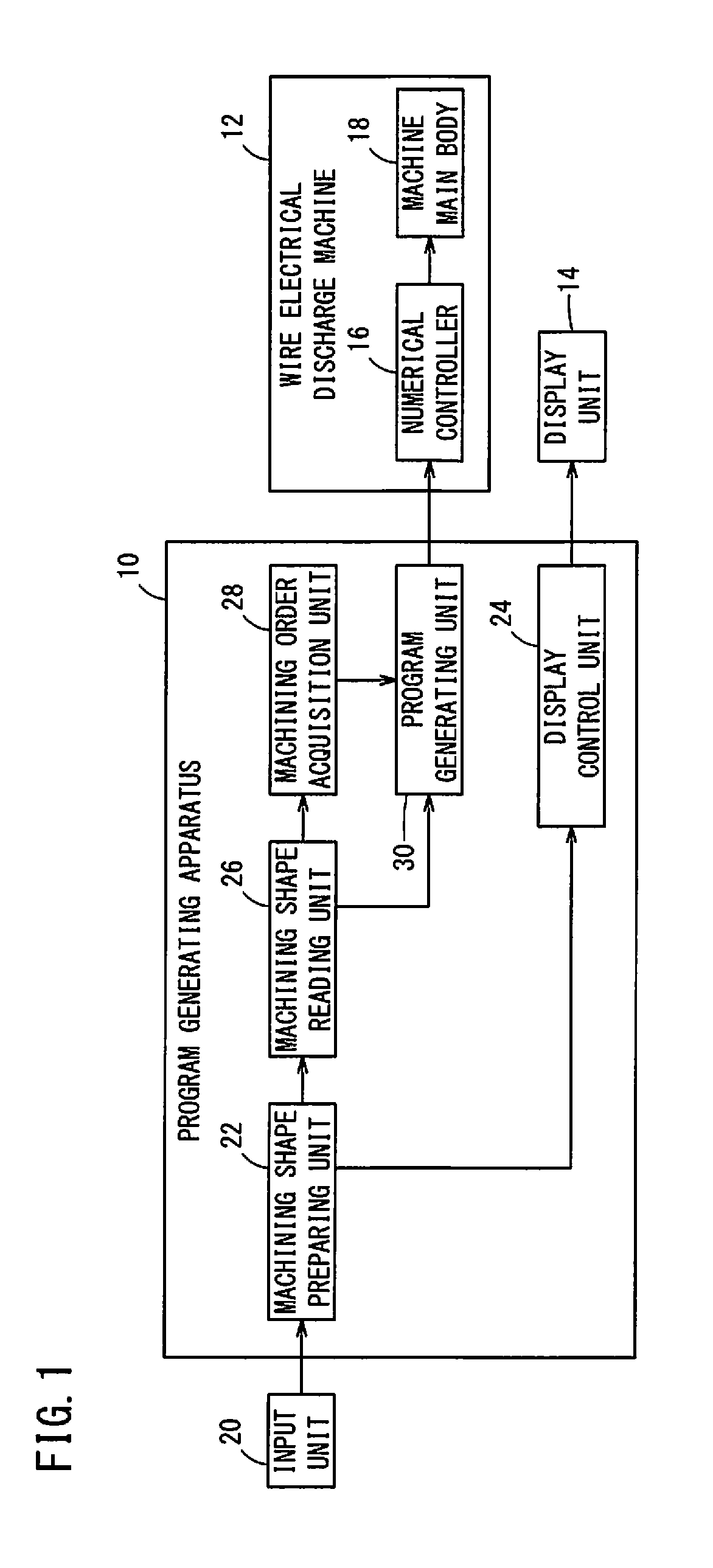
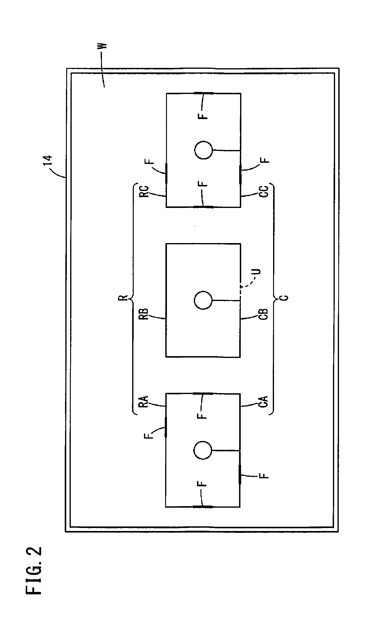
[0015]FIG. 1 is a block diagram showing a program generating apparatus 10 and a wire electrical discharge machine 12. FIG. 2 is a diagram showing an example of machining paths R and cores C in a workpiece W displayed on a display unit 14. In the example of FIG. 2, the workpiece W has machining paths RA, RB and RC for defining a machining shape. When rough machining is performed on the workpiece W, cores CA, CB and CC are produced.

[0016]Hereinbelow, as shown in FIG. 2, a machining path R indicates a single continuous line on a plane of the workpiece W, and a route drawn by such a single continuous line is counted as one machining path R. Therefore, the workpiece W shown in FIG. 2 contains three machining paths RA, RB, RC. In the following description, the person who performs operation or the like of the program generating apparatus 10 is referred to as a user, while the person who performs operation or the like of the wire electrical dis...

second embodiment

[0043]FIG. 4 is a block diagram showing a program generating apparatus 32, a program generating apparatus 10, and a wire electrical discharge machine 12.

[0044]The program generating apparatus32 is, for example, a personal computer or the like equipped with CAD / CAM software. The program generating apparatus 32 generates an NC program for controlling the wire electrical discharge machine 12 according to machining paths R on the workpiece W, which are input by the user.

[0045]The program generating apparatus 10 is a personal computer or the like equipped with CAD / CAM software. The program generating apparatus 10 reads an NC program generated by the program generating apparatus 32, and modifies the NC program. The program generating apparatus 32 and the program generating apparatus 10 may be personal computers or the like on which the same application is installed. For example, the program generating apparatus 32 may be used in an office by a user in charge of programming while the progr...


PUM


Abstract

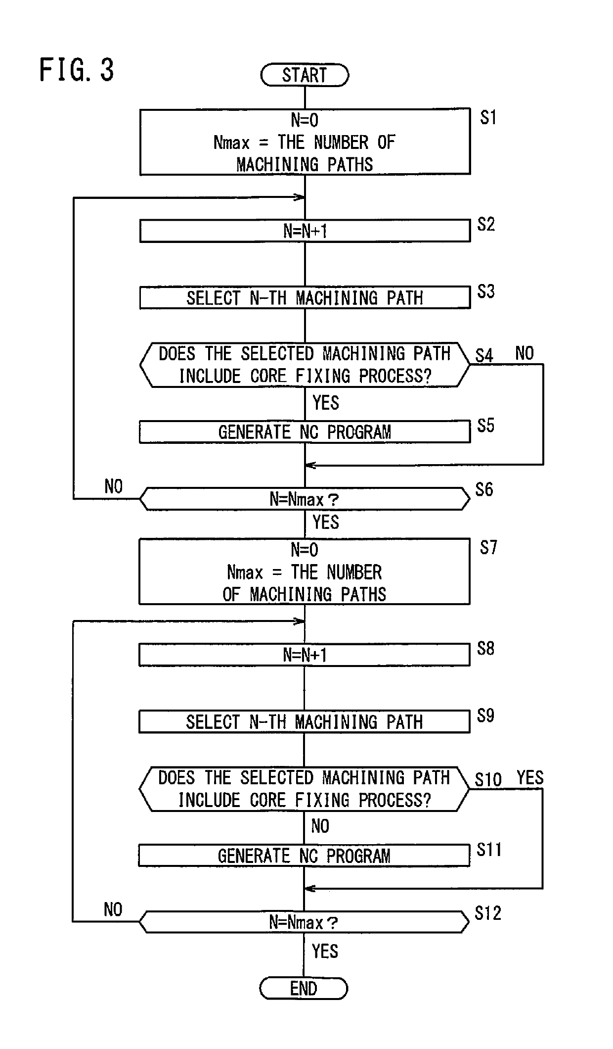
A program generating apparatus for generating an NC program for controlling a wire electrical discharge machine includes a machining order acquisition unit configured to acquire order in which a plurality of machining paths should be machined, the order being determined based on a predetermined rule, and a program generating unit configured to automatically change the order acquired by the machining order acquisition unit, so as to perform fixing process for fixing a core, which is produced during machining of a workpiece, to the workpiece by depositing a component of a wire electrode, prior to performing uncut process for leaving part of the core uncut, and generate an NC program for machining the machining paths in the changed order.

Description

CROSS-REFERENCE TO RELATED APPLICATION[0001]This application is based upon and claims the benefit of priority from Japanese Patent Application No. 2017-194768 filed on Oct. 5, 2017, the contents of which are incorporated herein by reference.BACKGROUND OF THE INVENTIONField of the Invention[0002]The present invention relates to a program generating apparatus and a program generating method for generating a program for controlling a wire electrical discharge machine.Description of the Related Art[0003]Japanese Patent No. 5269258 discloses a machining program generating apparatus for generating a machining program which performs control of machining so as to designate a core fixing machining part on a CAM apparatus and perform core fixing machining on the designated core fixing machining part.SUMMARY OF THE INVENTION[0004]For fixing a core to a workpiece, a fixing process for depositing a component from the wire electrode onto the core and the workpiece in a gap or kerf between them, o...

Claims


Application Information

Patent Timeline
IPC IPC(8): G05B19/4155
CPCG05B19/4155G05B2219/45221G05B2219/36031G05B19/4097G05B2219/31418B23H7/04B23H7/20B23H11/00G05B19/40937G05B2219/36301Y02P90/02G05B19/0426G05B19/102G05B19/106
Inventor ABE, HIROYUKI
Owner FANUC LTD
Learn More