Hair dryer

a hair dryer and dryer technology, applied in the field of hair dryers, can solve the problems of excessive power consumption of the hair dryer, affecting the hygiene of the hair or the hygiene of the scalp or face, and dust collecting in the air

Inactive Publication Date: 2019-04-18
LIM SEUNG PHILL
View PDF2 Cites 5 Cited by
  • Summary
  • Abstract
  • Description
  • Claims
  • Application Information

AI Technical Summary

Benefits of technology

[0011]The present invention has been conceived to overcome the above-described problems, and an object of the present invention is to provide hair dryer technology that can introduce and blow external air by means of a difference in air pressure and that can also solve noise and vibration problems.

Problems solved by technology

However, the conventional hair drying method is designed to draw air in a surrounding space and discharge the drawn air at high speed through a small outlet due to the structure of the hair dryer.
Accordingly, problems arise in that dust in the air is gathered by the suction force of the blower fan and discharged to the head, face, etc. of a user and in that dust, hair, etc. introduced into the air flow path are burned by the heating coil and blown in the form of dust.
There is possibility that foreign materials, such as dust and hair, may be introduced into the heating coil and discharged in the form of fine contaminants, such as ashes, and thus the fine pollutants may affect the hygiene of the hair or the hygiene of the scalp or face.
Accordingly, in order to secure the rotational driving force of the blowing fan, the power consumption of the hair dryer becomes excessively high, and also noise and vibration problems may occur due to the blowing fan rotating at high speed.
Furthermore, the inlet of air to be blown is provided in the grip, and thus a problem arises in that when the hair dryer is used, the inflow path of external air is rarely maintained without interference due to a user's gripping operation.

Method used


Image

  • Hair dryer
  • Hair dryer
  • Hair dryer

Examples


Embodiment Construction

[0031]Embodiments of the present invention will be described in detail with reference to the accompanying drawings, but descriptions of well-known technical parts will be omitted or abridged for brevity of description.

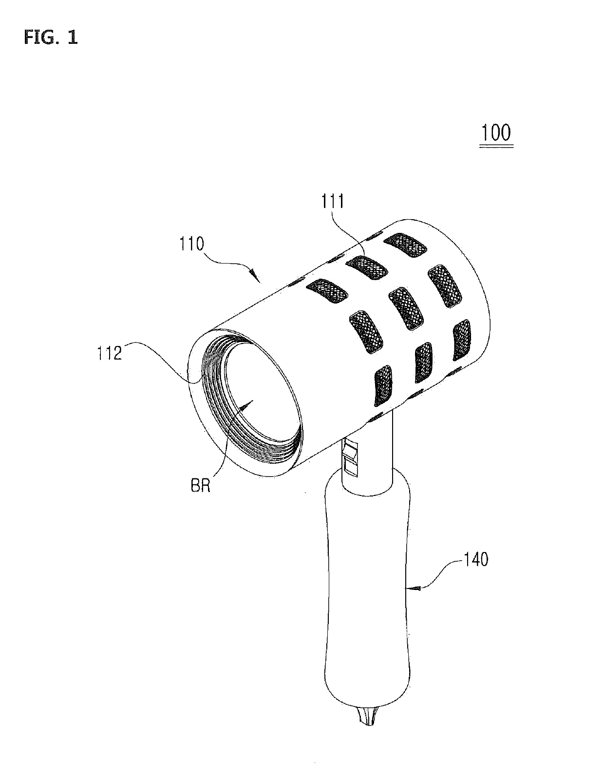
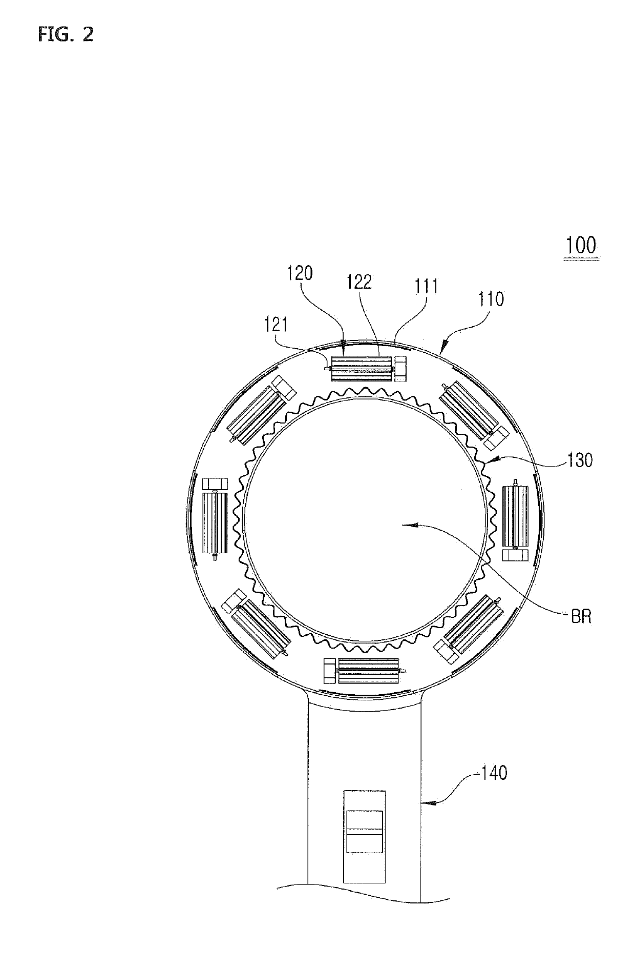
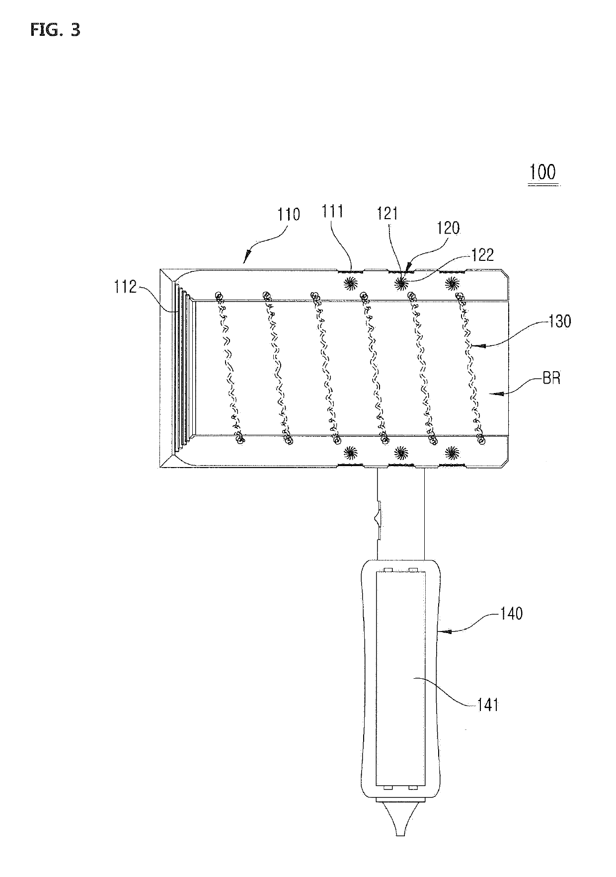
[0032]FIG. 1 is a perspective view of a hair dryer 100 having a plurality of blower fans according to an embodiment of the present invention, FIG. 2 is a cross sectional view of the hair dryer 100 having a plurality of blower fans according to the embodiment of the present invention, and FIG. 3 is a longitudinal sectional view of the hair dryer 100 having a plurality of blower fans according to the embodiment of the present invention.

[0033]As shown in FIGS. 1 to 3, in order to blow hot air to the hair of a user, the hair dryer 100 according to the present embodiment includes a plurality of blower fans 120 provided along the cylinder of a body 110, and functions to introduce external air in a direction traversing the air flow path BR of the dryer and to blow the externa...


PUM


Abstract

Disclosed herein is a hair dryer. The hair dryer includes: a body provided in a cylindrical shape having an annular sectional surface, configured to form an air flow path, and provided with one or more air inlets and an air outlet; a blower fan provided between the air inlets and the air outlet, and configured to be rotated to thus introduce external air into the body and blow the external air; and a heating coil provided between the blower fan and the air outlet, and configured to heat the external air; wherein air outside the air flow path is introduced into the air flow path and blown to the user along with the air being blown via the air outlet by means of a difference in air pressure between the inside region of the air flow path and a region outside the air flow path.

Description

CROSS-REFERENCE TO RELATED APPLICATION[0001]This application claims the benefit of Korean Patent Application No. 10-2017-0134389, filed on Oct. 17, 2017, which is hereby incorporated by reference herein in its entirety.BACKGROUND1. Technical Field[0002]The present invention relates to a hair dryer.2. Description of the Related Art[0003]The hairstyle that can change the appearance of a person can deform the shape of the hair made of protein by means of hot air or heat via a hair dryer or curling iron, thereby enabling styling that is suitable for a user's personal preference.[0004]A conventional hair dryer adopts a method of generating high-temperature hot air by simply heating incoming external air by means of a heating coil contained in an air flow path when the external air is introduced into the air flow path and blown via a blower fan.[0005]However, the conventional hair drying method is designed to draw air in a surrounding space and discharge the drawn air at high speed throug...

Claims


Application Information

Patent Timeline
Patent Type & Authority Applications(United States)
IPC IPC(8): A45D20/12
CPCA45D20/12A45D20/10A45D20/04F26B3/06
Inventor LIM, CHAEHYUNLIM, SEUNG PHILL
Owner LIM SEUNG PHILL
Why Eureka
Try Eureka