Bearing arrangement for fluid machinery application

a technology for bearings and fluid machinery, applied in the direction of roller bearings, mechanical equipment, rotary machine parts, etc., can solve the problems of increasing the cost of manufacturing, mounting, and servicing of wind turbines, cumbersome and costly attachment of load bearing rolling bearings to the rotor shaft and to the support structure, and improving the mounting process. , the effect of improving the bearing arrangemen

Active Publication Date: 2019-04-18
AB SKF
View PDF16 Cites 2 Cited by
  • Summary
  • Abstract
  • Description
  • Claims
  • Application Information

AI Technical Summary

Benefits of technology

[0015]In view of the above-mentioned and other drawbacks of the prior art, a general object of the present invention is to provide an improved and robust bearing arrangement for a fluid machinery application and a fluid machinery application including such bearing arrangement. The bearing arrangement allows for improved mounting / dismounting of the bearing arrangement in relation to a rotor shaft and / or support structure supporting the rotor shaft.

Problems solved by technology

Moreover, the weight and size of the components as well as the location of the rotor arrangement in tower-like structures increase the cost for manufacturing, mounting, and servicing of the wind turbines.
In particular, the attachment of load bearing rolling bearings to the rotor shaft and to support structures is cumbersome and costly, typically involving heating techniques of members, such as the inner ring of a rolling bearing to be mounted, in order to provide suitable attachment and pre-stressing, while maintaining a high level of precision to ensure a correct alignment and orientation of the rolling bearing in relation to the shaft and / or support structure.
As a result, the mounting process is complicated and time-consuming, and often requires auxiliary equipment for heating and alignment control measurements.
Also, in the hitherto known solutions, the dismounting of the load bearing rolling bearings from the rotor shaft or from the support structures is cumbersome and time-consuming.
In other words, mounting and dismounting of the rotor arrangement and the bearing typically require advanced application engineering, while posing high quality requirements on the surrounding parts of the system.
Any excessive axial play may considerably reduce the life time of the application arrangement.
Accordingly, hitherto known bearing solutions for fluid machinery applications involving an axially locating roller bearing are considered to suffer from overdesigning in relation to e.g. radial load bearing capacity.
Similarly, many of those bearings are non-compact including large bearing designs in order to provide a sufficient axial load bearing capacity.
In this manner, this type of bearing is considered to occupy valuable space in the fluid machinery arrangement.
Furthermore, larger bearings are more expensive to produce due to high material costs, while the high bearing mass may have a negative impact on the operational efficiency by e.g. increasing the rotational inertia of the arrangement.

Method used


Image

  • Bearing arrangement for fluid machinery application
  • Bearing arrangement for fluid machinery application
  • Bearing arrangement for fluid machinery application

Examples


Embodiment Construction

[0099]The present invention will now be described more fully hereinafter with reference to the accompanying drawings, in which exemplary embodiments of the invention are shown. The invention may, however, be embodied in many different forms and should not be construed as limited to the embodiments set forth herein; rather, these embodiments are provided for thoroughness and completeness. Like reference characters refer to like elements throughout the description.

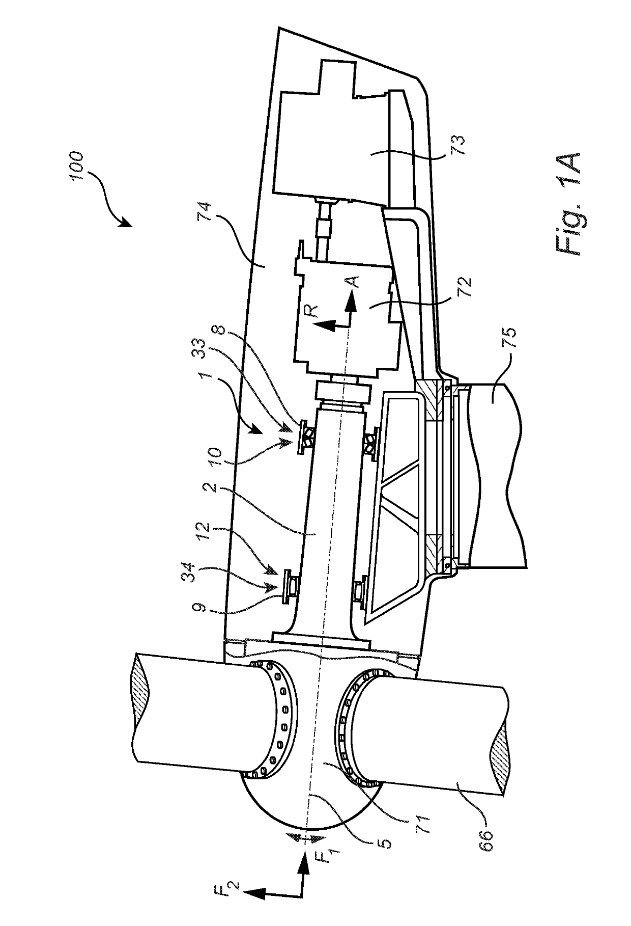
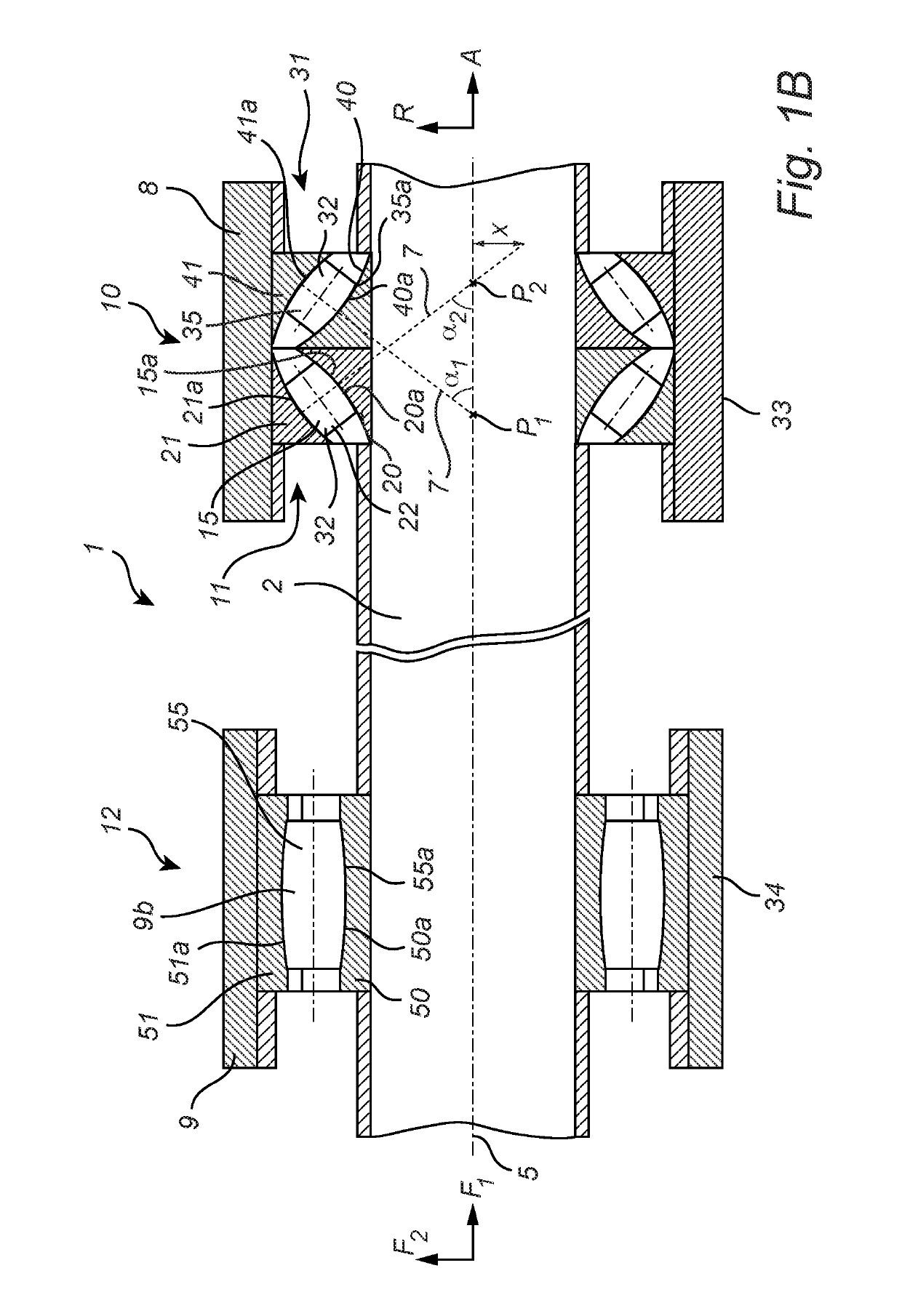
[0100]Referring now to the figures and FIGS. 1a-1b in particular, there is depicted a bearing arrangement for a fluid machinery application according to an example embodiment of the present invention.

[0101]Although the following description has been made on a wind turbine arrangement, the present invention may as well be implemented in a water turbine arrangement. In addition, the present invention may also be implemented in a propulsion turbine arrangement. As used herein, the term “fluid machinery application” therefore me...


PUM


Abstract

A bearing arrangement for a fluid machinery application employing an axially locating bearing. The axially locating bearing includes: a first angular self-aligning contact bearing arranged next to a second angular self-aligning contact bearing. Each of the first angular self-aligning contact bearing and the second angular self-aligning contact bearing includes a set of rolling elements arranged in a row and interposed between a respective curved inner raceway and an associated curved outer raceway. Each roller is a symmetrical cylindrically-shaped roller having a curved raceway-contacting surface. Each roller is inclined respective to the axial direction of the shaft by a respective contact angle. The rollers support an axial force and a radial force. The axially non-locating bearing position is arranged spaced apart from the axially locating bearing position, as seen in the axial direction. Examples of fluid machinery applications include: a wind turbine, water turbine or a propulsion turbine.

Description

CROSS REFERENCE TO RELATED APPLICATIONS[0001]This application is a Continuation of U.S. patent application Ser. No. 14 / 535,451, filed on 7 Nov. 2014, which claims the benefit of Sweden (SE) Patent Application Number 1300695-2, filed on 7 Nov. 2013, the contents of which are both fully incorporated herein by reference.FIELD OF THE INVENTION[0002]The present invention pertains to a bearing arrangement for a fluid machinery application, such as a wind turbine arrangement, a water turbine arrangement or a propulsion turbine arrangement. More specifically, the bearing arrangement includes an axially locating bearing position and an axially non-locating bearing position which are capable of supporting axial loads and restricting axial movement of a shaft, such as a rotor shaft of the fluid machinery application.[0003]Moreover, the present invention pertains to a fluid machinery application, such as a wind turbine arrangement, a water turbine arrangement or a propulsion turbine arrangement...

Claims


Application Information

Patent Timeline
Patent Type & Authority Applications(United States)
IPC IPC(8): F16C19/54F16C19/38
CPCF16C19/542F16C19/38F16C19/545Y02E10/722F16C2240/34F16C2360/31F16C2300/14F16C19/36F16C23/08Y02E10/72
Inventor KULLIN, ARNE LARS JONASREICHERT, JUERGENWENDEBERG, HANS
Owner AB SKF
Why Eureka
Try Eureka