Protection Device for a Valve Positioner

a protection device and positioner technology, applied in the direction of valve housing, hose connection, water supply installation, etc., can solve the problems of corroding the positioner, reducing the performance of the positioner, affecting the service life of the positioner, etc., to achieve the effect of reducing the time of maintenance/repair and complete failure, time-consuming and expensive, and reducing the service li

Inactive Publication Date: 2013-12-26
AEGIS FLOW TECH L L C
View PDF22 Cites 3 Cited by
  • Summary
  • Abstract
  • Description
  • Claims
  • Application Information

AI Technical Summary

Benefits of technology

[0014]Accordingly, an improved and more robust protection device and method of using a protection device with a valve positioner are provided that are capable of protecting a valve positioner in demanding environmental and operating conditions while also allowing for maintenance and inspection of the positioner without removing it from service. The protection device includes a housing configured to protect the valve positioner from external corrosion. The housing includes a top base, a bottom base and a central body extending between the top base and the bottom base. The central body may be joined to an edge of the top base and an edge of the bottom base thereby forming a perimeter circumscribing the top base and the bottom base. The housing is preferably configured is configured to allow the atmosphere inside the housing to be purged and replaced. In an embodiment, the housing may also be at least partially constructed from a substantially transparent thermoplastic material to allow for inspection of the valve positioner without removing the housing.

Problems solved by technology

A common problem faced in the industry is corrosion of the positioner, gauges and the fasteners as a result of operating in very demanding environments, e.g. outdoors in weather, extreme temperature and / or corrosive environments.
In these environments, especially in atmospheres containing corrosive substances such as salts and chemicals (e.g. caustic), positioners often become damaged, which can lead to diminished positioner performance, maintenance / repair and complete failure.
This is often time consuming and expensive.
However, although the corrosion resistant materials provide an added measure of protection in demanding operating environments, the valve positioner and its ports can still become damaged over time requiring the positioner to be completely removed from service for repair or replacement.

Method used


Image

  • Protection Device for a Valve Positioner
  • Protection Device for a Valve Positioner
  • Protection Device for a Valve Positioner

Examples


Embodiment Construction

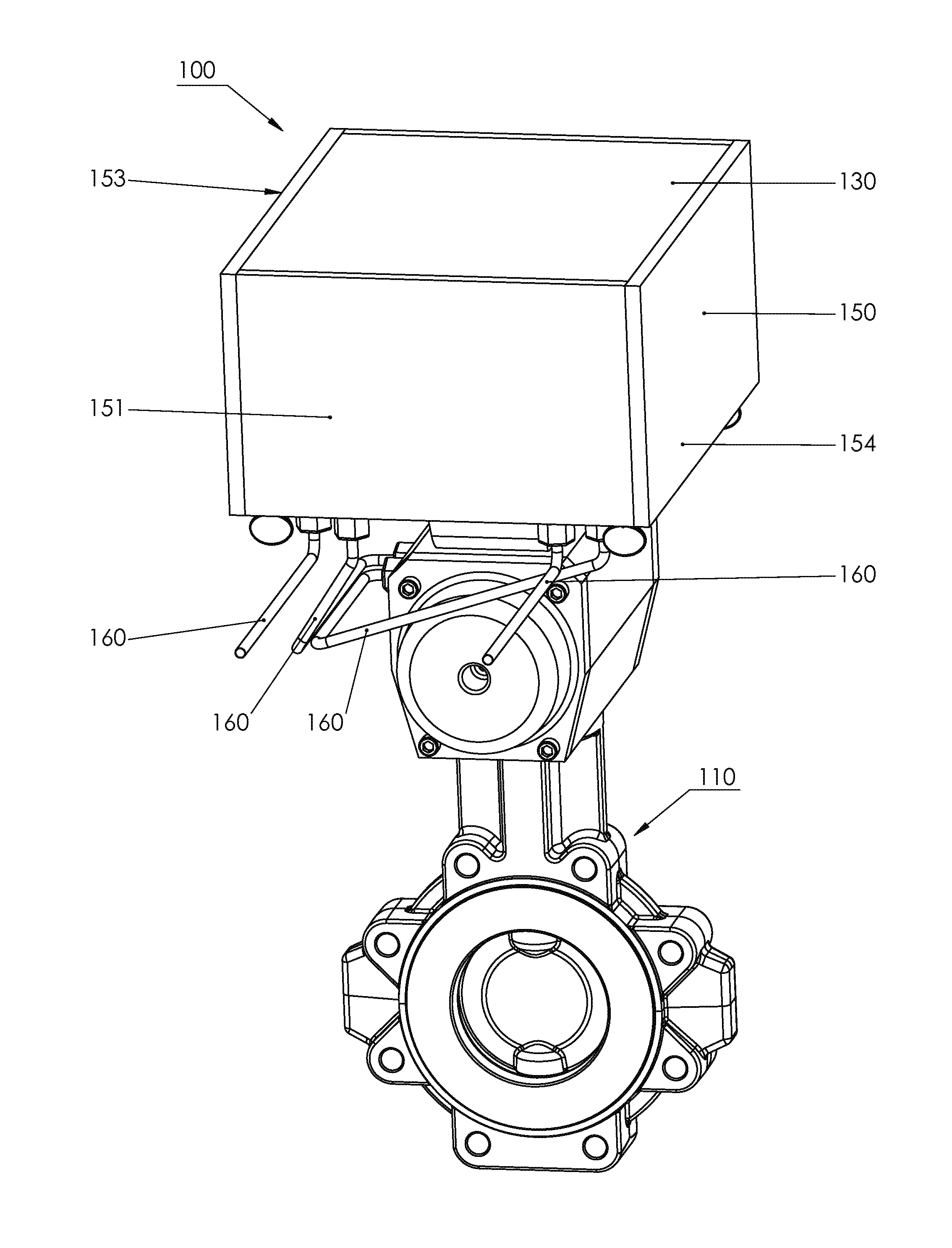
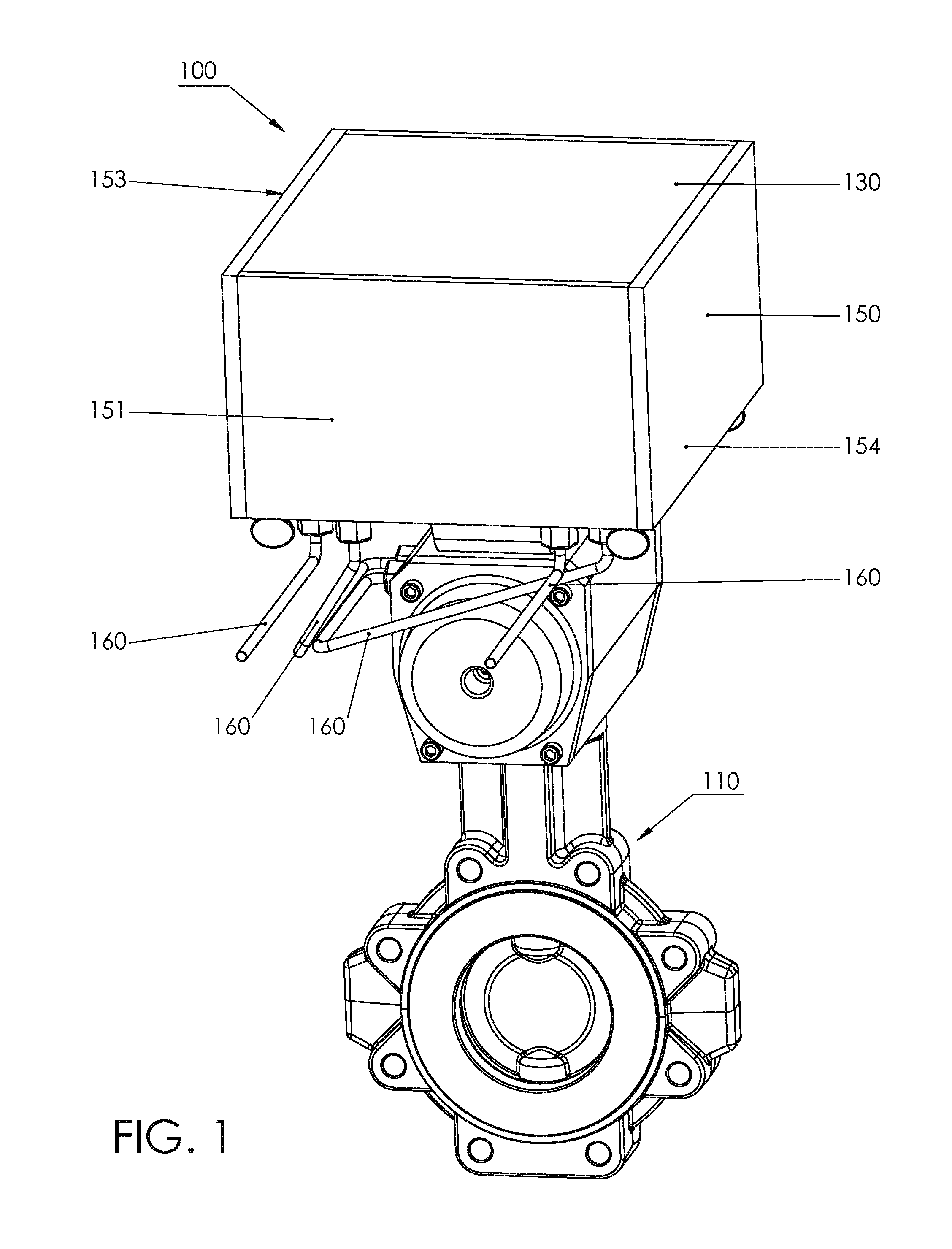
[0028]The claimed subject matter is now described with reference to the drawings, wherein like reference numerals are used to refer to like elements throughout. An embodiment of a protection device for a valve positioner in accordance with this invention is shown generally in FIG. 1 at 100.

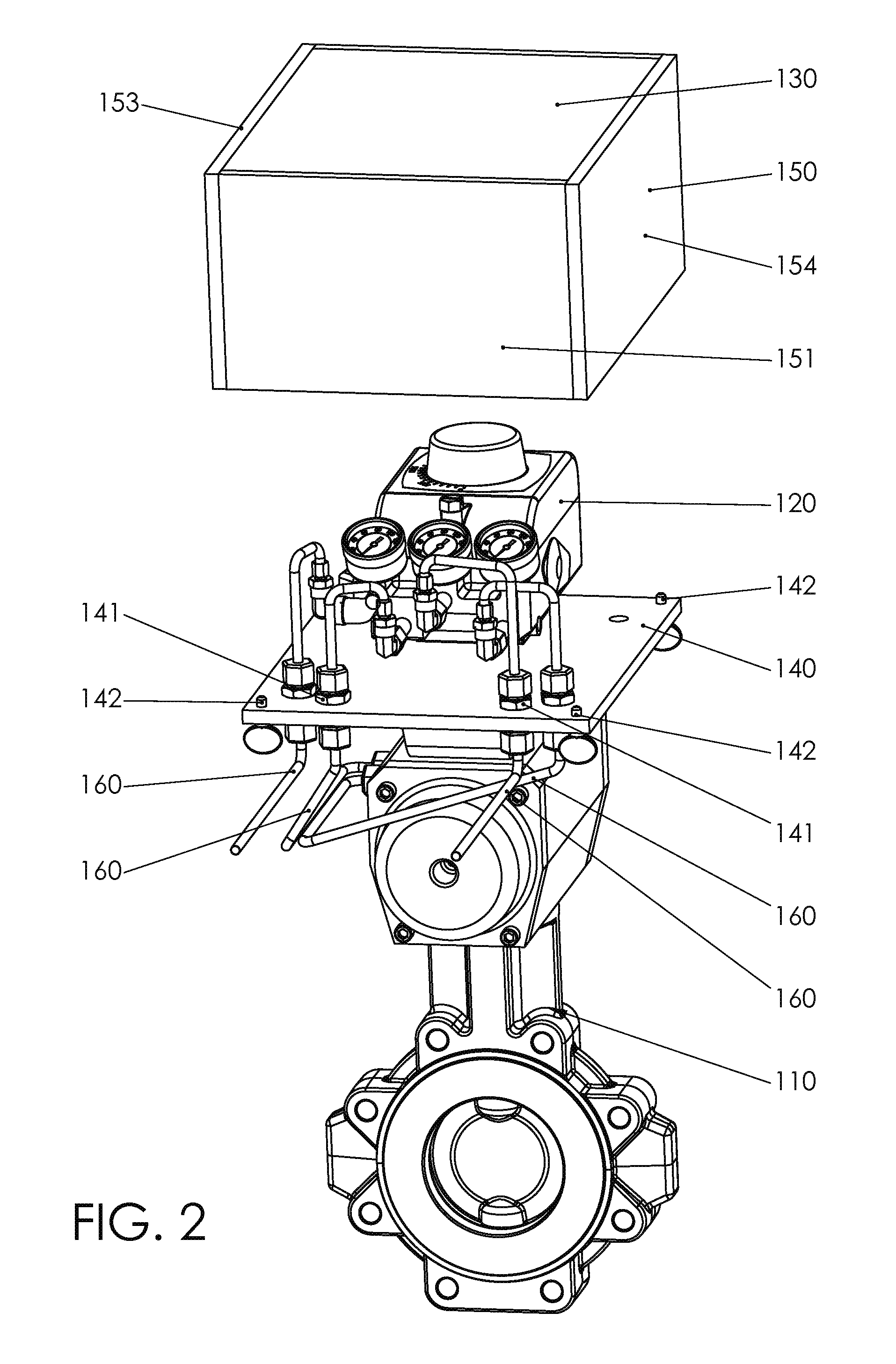
[0029]With reference initially to FIGS. 1-6, the protection device (100) comprises a housing configured to substantially protect a valve positioner (120) from external corrosion. As shown in FIG. 5, when the housing is in place around said valve positioner, a void is defined between the housing and the valve positioner (120). The protection device (100) may be secured to the valve (110), preferably secured to the valve actuator (111) or yoke. The housing comprises a top base (130), a bottom base (140), and a central body (150) that extends between the top base (130) and the bottom base (140). The central body (150) is joined to the top base and the bottom base to form a perimeter that circumscribe...


PUM

PropertyMeasurementUnit
perimeteraaaaaaaaaa
corrosionaaaaaaaaaa
thermoplasticaaaaaaaaaa

Abstract

An improved and more robust protection device capable of protecting a valve positioner in demanding environmental and operating conditions while also allowing for maintenance and inspection of the positioner without removing it from service. The protection device includes a housing configured to protect the valve positioner from external corrosion. The housing includes a top base, a bottom base and a central body extending between the top base and the bottom base. The central body may be joined to an edge of the top base and an edge of the bottom base thereby forming a perimeter circumscribing the top base and the bottom base.

Description

CROSS-REFERENCE TO RELATED APPLICATION[0001]Not Applicable.STATEMENT REGARDING FEDERALLY SPONSORED RESEARCH OR DEVELOPMENT[0002]Not applicable.THE NAMES OF THE PARTIES TO A JOINT RESEARCH AGREEMENT[0003]Not applicable.INCORPORATION-BY-REFERENCE OF MATERIAL SUBMITTED ON A COMPACT DISC[0004]Not applicable.BACKGROUND OF THE INVENTION[0005]1. Field of the Invention[0006]The present disclosure relates to protection devices for a valve element, in particular an enclosure or housing for protecting a valve positioner or position indicator in a demanding operating environment.[0007]2. Description of Related Art[0008]Valve positioners and position indicators are often used in control valve applications to control the open / closed position of a valve in response to an input signal. The valve positioner automatically adjusts its output to the actuator to maintain the desired position in proportion to the input signal. Valve positioners are usually mechanically connected to the valve stem or actu...

Claims


Application Information

Patent Timeline
Patent Type & Authority Applications(United States)
IPC IPC(8): F16P1/00B23P17/04
CPCF16P1/02F16K27/12Y10T29/49826Y10T137/7043
Inventor CROCHET, SR., KEVIN W.EGER, NORMANROVIRA, III, SIDNEY A.
Owner AEGIS FLOW TECH L L C
Why Eureka
Try Eureka