Vehicle Shifter Mechanism with Shifter Lever Fitting

Active Publication Date: 2019-04-18
LOKAR
View PDF0 Cites 1 Cited by
  • Summary
  • Abstract
  • Description
  • Claims
  • Application Information

AI Technical Summary

Benefits of technology

[0009]The following example embodiments are representative of example techniques and structures designed to carry out the objects of the present general inventive concept, but the present general inventive concept is not limited to these example embodiments. In the accompanying drawings and illustrations, the sizes a

Problems solved by technology

This presents numerous disadvantages during installation.
For example, these designs do not allow for selective rotatable orientation of the lever and/or shifter knob once the knob is fully threaded onto the lever and the lever is fully threaded into the shifter device.
In installation of such designs, rota

Method used


Image

  • Vehicle Shifter Mechanism with Shifter Lever Fitting
  • Vehicle Shifter Mechanism with Shifter Lever Fitting
  • Vehicle Shifter Mechanism with Shifter Lever Fitting

Examples


Example

[0015]Reference will now be made to the example embodiments of the present general inventive concept, examples of which are illustrated in the accompanying drawings and illustrations. The example embodiments are described herein in order to explain the present general inventive concept by referring to the figures. The following detailed description is provided to assist the reader in gaining a comprehensive understanding of the structures and fabrication techniques described herein. Accordingly, various changes, modification, and equivalents of the structures and fabrication techniques described herein will be suggested to those of ordinary skill in the art. The progression of fabrication operations described are merely examples, however, and the sequence type of operations is not limited to that set forth herein and may be changed as is known in the art, with the exception of operations necessarily occurring in a certain order. Also, description of well-known functions and construc...


PUM


Abstract

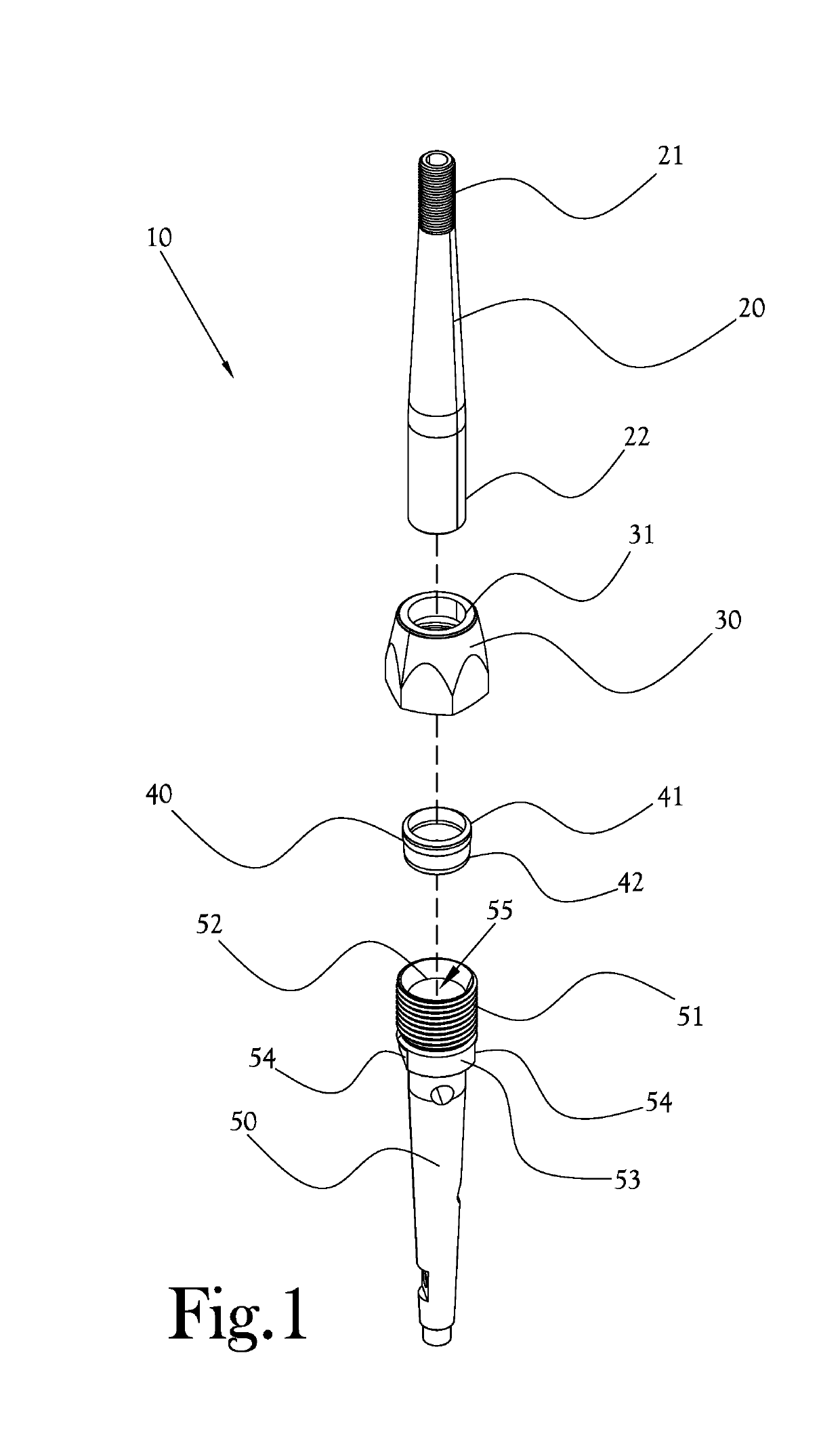
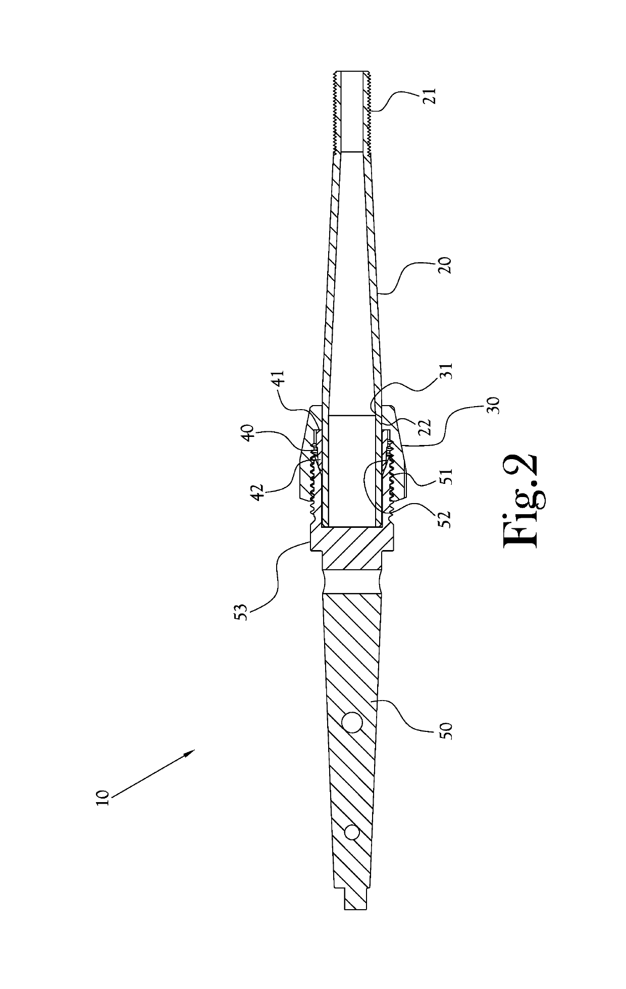
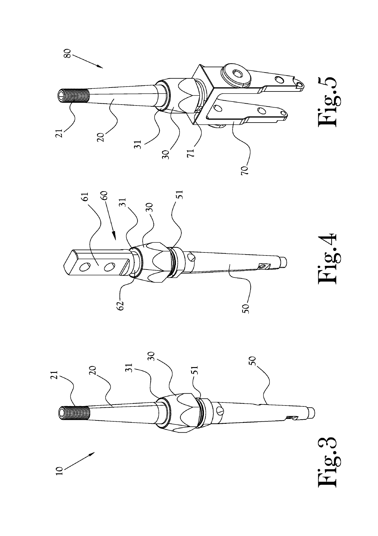
A vehicle shifter mechanism comprises a shift control member configured with an outer threaded portion proximate an upper end, and an inwardly tapered bore proximate the upper end. A shift lever is configured with an outwardly extending annular shoulder proximate a lower end. The annular shoulder has a tapered lower portion configured to register with the tapered bore of the shift control member. A locking nut is configured to fit over the shift lever and to mate with the threaded portion of the shift control member to compress the tapered lower portion of the annular shoulder to the tapered bore to fix the shift control member to the shift lever.

Description

CROSS-REFERENCE TO RELATED APPLICATIONS[0001]This application claims the benefit of U.S. Provisional Patent Application No. 62 / 573,505, filed on Oct. 17, 2017STATEMENT REGARDING FEDERALLY-SPONSORED RESEARCH OR DEVELOPMENT[0002]Not ApplicableBACKGROUND OF THE INVENTION1. Field of Invention[0003]The present general inventive concept relates to vehicle shifter mechanisms, and, more particularly, to a coupling for a shifter lever portion of a shifter mechanism which allows for convenient installation of a shifter lever in a vehicle.2. Description of the Related Art[0004]Vehicle shifters of the type having a lever configured to allow a user to shift gears and / or shift automatic transmission settings of the vehicle are known generally in the art. Typical prior art designs for vehicle shifters often incorporate a “boot” portion which is mounted to an interior surface of a vehicle. The boot portion surrounds a lower portion of a shift lever which is coupled through appropriate linkages to a...

Claims


Application Information

Patent Timeline
IPC IPC(8): F16H59/10F16B37/00
CPCF16H59/10F16B37/00F16H59/0278F16L19/061F16L19/065F16B7/149
Inventor FORD, KEVIN S.WALLS, VAN
Owner LOKAR
Why Eureka
Try Eureka