Display apparatus and protection circuit thereof

Active Publication Date: 2018-11-15
AU OPTRONICS CORP
View PDF0 Cites 1 Cited by
  • Summary
  • Abstract
  • Description
  • Claims
  • Application Information

AI Technical Summary

Benefits of technology

[0007]To achieve the foregoing objective, a technical aspect of the present disclosure relates to a protection circuit, applied to a display apparatus. The display apparatus includes a voltage level shifter and a plurality of clock signal lines coupled to the voltage level shifter. The protection circuit includes a plurality of switches. At least one of the switches includes a control terminal, an input terminal, and an output terminal. The control terminal is coupled to a first clock signal line in the clock signal lines. The input terminal is coupled to a second clock signal line in the clock signal lines. The control terminal determines, according to a first clock signal provided by the first clock signal line, whether to conduct the input terminal and the output terminal, and the output terminal outputs a second clock signal provided by the second clock signal line. The output terminals of the switches are coupled to a node, and when the first clock signal line and the second clock signal line are short-circuited, the first clock signal and the second clock signal are pulled down as low-level signals, and the node outputs a protection signal.
[0008]To achieve the foregoing objective, another technical aspect of the present disclosure relates

Problems solved by technology

When the OCP solution is used, it is difficult to set a protection point thereof.
If the protection point is set extremely low, a faulty contact easily occurs, causing starting of the protection mechanism.
In addition, when the SCP solution is used, because the mechanism thereof is to detect a voltage level of an output path by using a shift register, once a position in which a short-circuit occurs is extremely distant from a shift register, the protection mechanism may not be effectively started ultimately due to trace impeda

Method used


Image

  • Display apparatus and protection circuit thereof
  • Display apparatus and protection circuit thereof
  • Display apparatus and protection circuit thereof

Examples


Example

[0017]According to a commonly used operation mode, features and elements in the figures are not drawn to scale, and the drawing manner thereof is to present specific features and elements related to the present disclosure in an optimal manner. In addition, similar elements / components are denoted by same or similar reference numerals in different drawings.

DETAILED DESCRIPTION

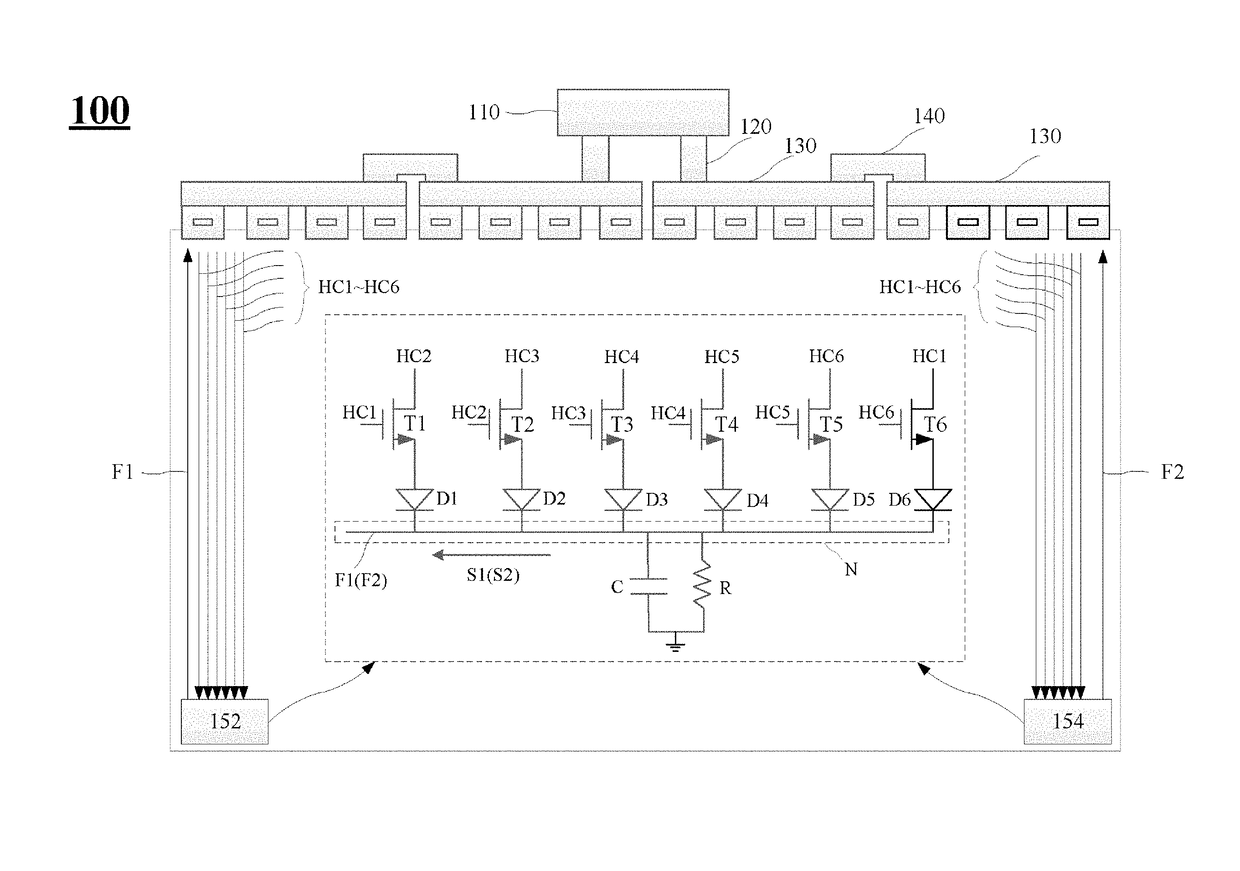
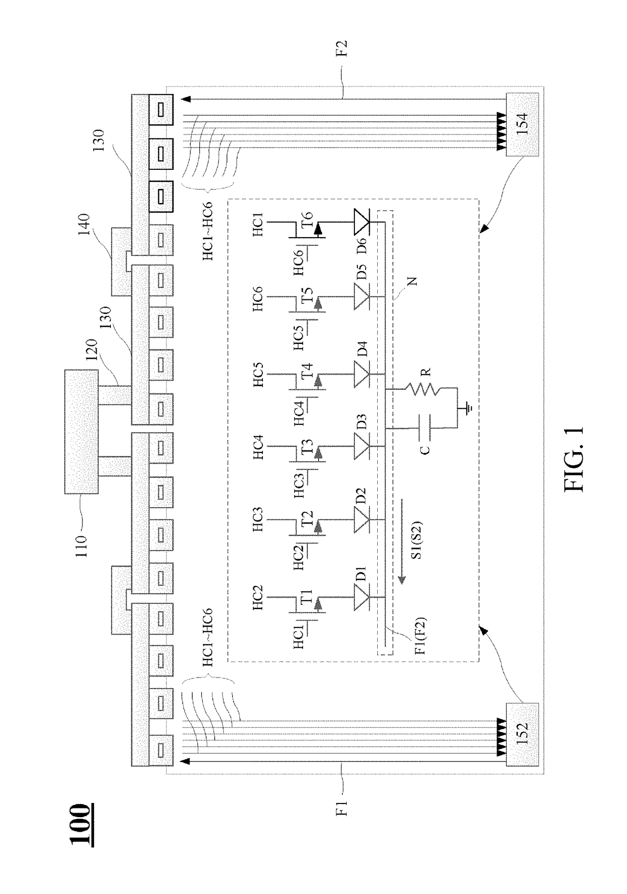
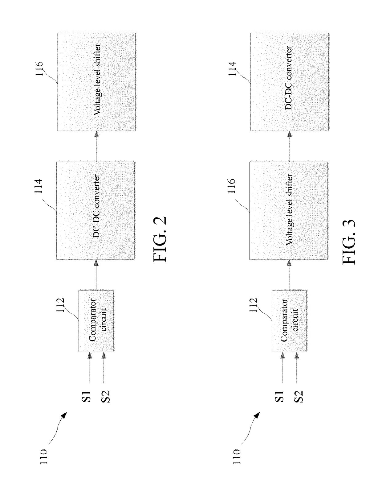
[0018]To make the descriptions of the present disclosure more detailed and complete, the following provides illustrative descriptions of the implementation aspects and the specific embodiments of the present disclosure. However, this is not the only form for implementing or applying the specific embodiments of the present disclosure. The implementations cover features of multiple specific embodiments and method steps used to construct and operate these specific embodiments and a sequence of the steps. However, other specific embodiments may also be used to achieve a same or equivalent function and step sequence.

[...


PUM


Abstract

A protection circuit is disclosed, applied to a display apparatus. The display apparatus includes a voltage level shifter and a plurality of clock signal lines coupled to the voltage level shifter. The protection circuit includes a plurality of switches. At least one of the switches includes a control terminal, an input terminal, and an output terminal. The control terminal is coupled to a first clock signal line in the clock signal lines. The input terminal is coupled to a second clock signal line in the clock signal lines. The control terminal determines, according to a first clock signal provided by the first clock signal line, whether to conduct the input terminal and the output terminal, and the output terminal outputs a second clock signal provided by the second clock signal line. The output terminals of the switches are coupled to a node, and when the first clock signal line and the second clock signal line are short-circuited, the first clock signal and the second clock signal are pulled down as low-level signals, and the node outputs a protection signal.

Description

BACKGROUNDTechnical Field[0001]The present disclosure relates to a display apparatus, and in particular, to a display apparatus having a protection circuit.Related Art[0002]In a display technology, there are several solutions for short circuit protection, such as over current protection (OCP), short circuit protection (SCP), and a current limiting resistor. When the OCP solution is used, it is difficult to set a protection point thereof. If the protection point is set extremely low, a faulty contact easily occurs, causing starting of the protection mechanism. On the contrary, if the protection point is set extremely high, the protection mechanism is likely not normally started even if a short-circuit already occurs in a display.[0003]In addition, when the SCP solution is used, because the mechanism thereof is to detect a voltage level of an output path by using a shift register, once a position in which a short-circuit occurs is extremely distant from a shift register, the protectio...

Claims


Application Information

Patent Timeline
IPC IPC(8): G09G3/00H01L27/02
CPCG09G3/006H01L27/0255G02F2201/50G09G2330/045G09G2310/0289H02H7/20H03K17/08H03K17/082G09G2330/04H01L27/0266G02F1/136204G09G2330/08G09G2330/12
Inventor WU, JIAN-YUCHEN, SHIH-HSUAN
Owner AU OPTRONICS CORP
Why Eureka
Try Eureka