Electrical machines with reduced cogging

Active Publication Date: 2007-11-01
GE POWER CONVERSION
View PDF8 Cites 3 Cited by
  • Summary
  • Abstract
  • Description
  • Claims
  • Application Information

AI Technical Summary

Benefits of technology

[0034] The use of a star-connected 3-phase stator winding would ensure that the 3rd harmonic of the fundamental pole number frequency and its integral multiples (triple-n harmonics) could not flow in the stator current and that a generator with a stator winding connected in this way would not have triple-n harmonics in its line-line voltage waveform. This specific winding is given as an example only. The effect on the e.m.f. harmonics of different winding configurations and windings with different numbers of phases is well known and would be readily understood by those who are skilled in the art.
[0035] Alternatively, pitching the stator coils at two-thirds of the ref

Problems solved by technology

A common problem encountered in the operation of electrical machines is cogging.
Cogging during the operation of electrical machines can result in decreased efficiency and reliability, as well as causing unwanted vibration and noise and, in extreme cases, complete failure.
The effect is also well known in induction machines in which the magnet poles and winding slots interact to cause serious cogging for particular numbers of winding slots.
For example, it is known that when an electrical machine has a number of winding slots which is an integral multiple of the number of its magnet poles the magneto-motive force (m.m.f.) created by the machine's stator winding during operation will contain a minimised number of harmonics but the machine may also experience pronounced cogging during operation.
However, in some cases this may not be preferred, or even possible.
For example, in large-scale electrical machines the options for having differing numbers of winding slots that are not multiples of the number of magnet poles are very limited as the non-synchronous flux patterns that result from such changes in the number of winding slots inevitably lead to additional losses in the magnet poles.
These losses may be extremely high and even render the method unusable.
An alternative method of reduci

Method used


Image

  • Electrical machines with reduced cogging
  • Electrical machines with reduced cogging
  • Electrical machines with reduced cogging

Examples


Example

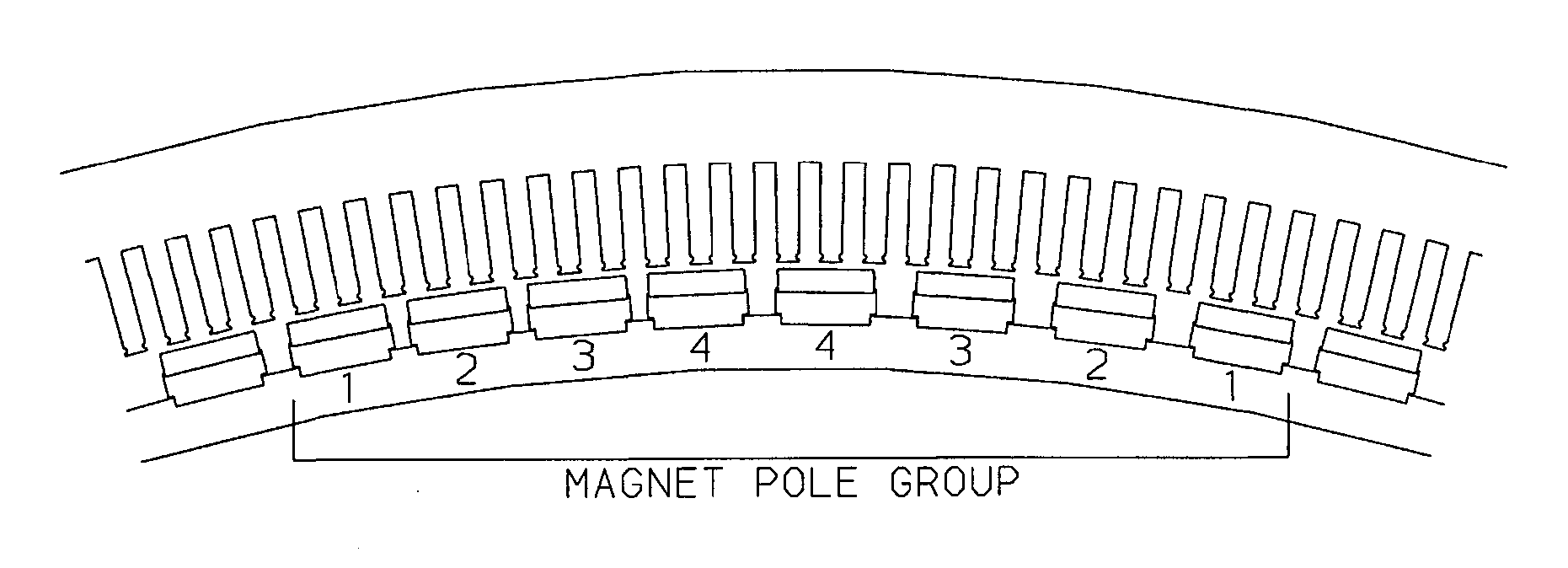
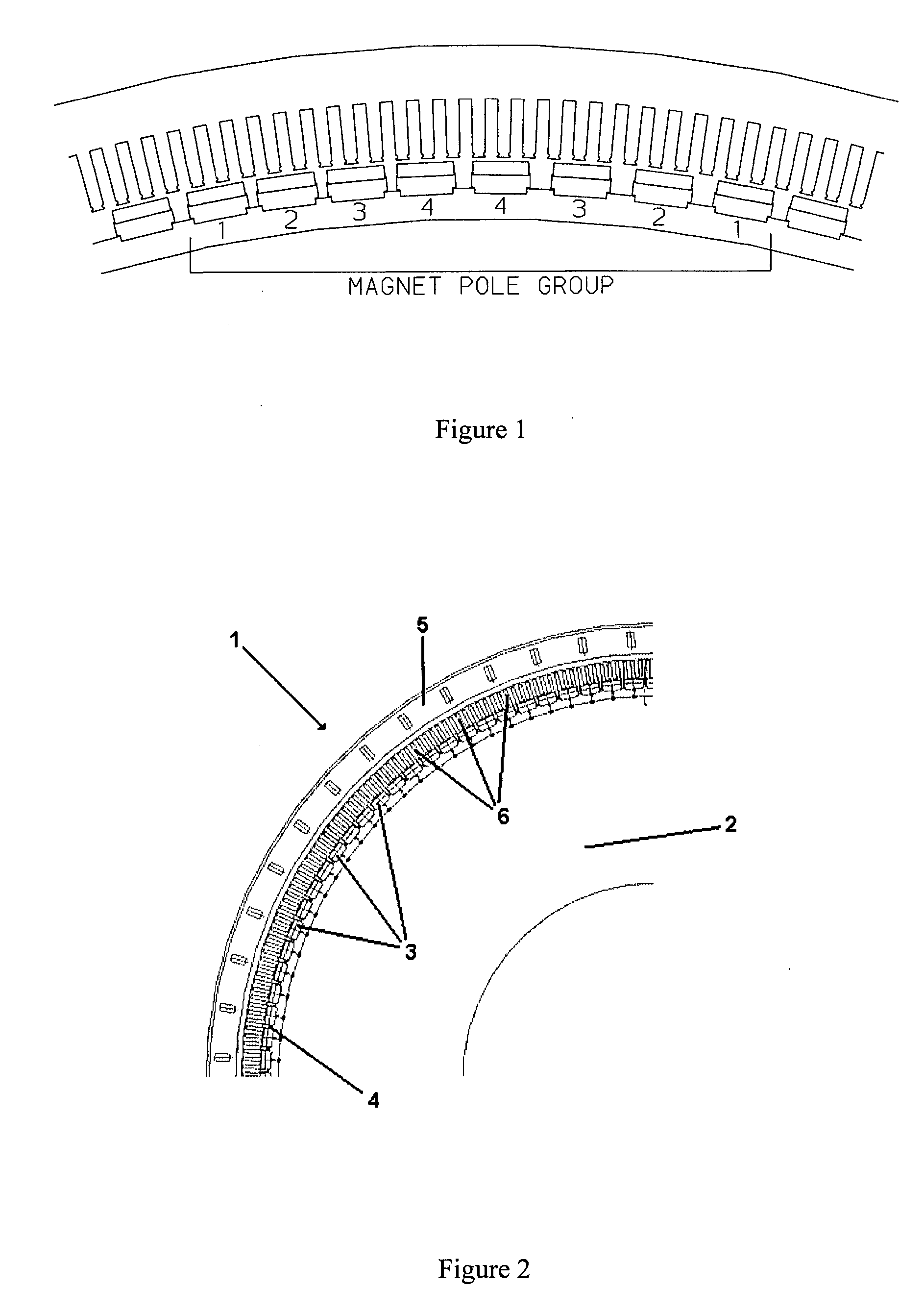
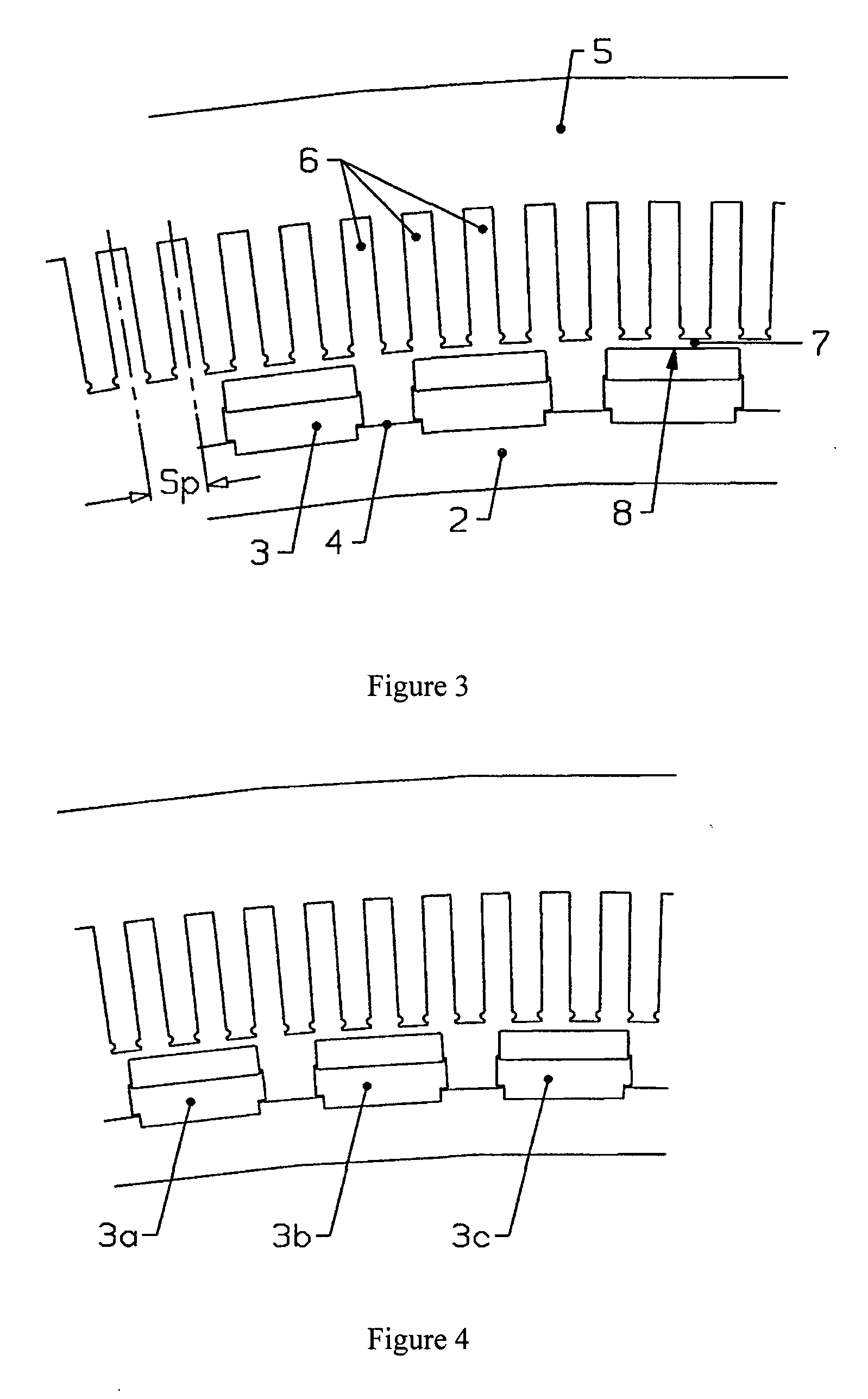
[0062] A typical conventional construction of a low-speed large-diameter electrical generator 1 is shown in FIGS. 2 and 3. The rotor 2 has one hundred and twelve magnet poles 3 mounted around its outer rim 4. The magnet poles 3 are equally spaced from each other such that they are equally spaced around the circumference of the rim 4. That is, the magnet poles 3 are each positioned in their reference positions and the reference angular magnet pole pitch is 3.21° (360° / 112). The rotor 2 is rotatably mounted within a stator 5 and there is an air gap 7 formed between the inner surface of the stator 5 and the outer surface 8 of the magnet poles 3. The stator 5 contains three hundred and thirty-six equally spaced winding slots 6 formed in its inner surface i.e. three winding slots per magnet pole. This equates to a reference angular winding slot pitch Sp of 1.07°, a third of the magnet pole pitch. Each winding slot 6 contains a portion of a stator winding (not shown) and the winding slots...


PUM


Abstract

The present invention provides an electrical machine 1 with reduced cogging. The magnet poles 3 of the electrical machine are comprised of at least two separate groups of at least two circumferentially adjacent magnet poles. One of the circumferentially outer magnet poles 3 in one of the groups of magnet poles is defined as being in its reference position. The reference position of each other magnet pole 3 is defined as the position each other magnet pole would occupy if all the magnet poles were equally circumferentially spaced around the first or second body and the one circumferentially outer pole was in its reference position. At least one of the circumferentially outer magnet poles 3 in each group is sited in its reference position. At least one magnet pole 3 in each group is a displaced magnet pole and is sited in a position that is displaced from its reference position by an amount that is not equal to an integral multiple of the reference angular pitch of the winding slots. The displacement of the magnet poles 3 provides a pronounced reduction in cogging.

Description

FIELD OF THE INVENTION [0001] This invention relates to permanent-magnet based, alternating current, rotating electrical machines and the minimising of cogging torque exhibited by such machines. In particular it relates to electrical machines with reduced cogging due to the displacement of their magnet poles. BACKGROUND OF THE INVENTION [0002] A common problem encountered in the operation of electrical machines is cogging. Cogging is the presence of non-linear magnetic torque during the operation of the machine due to the effect of the geometry of the rotor and the stator at the air gap on the flux distribution and the forces between the rotor and the stator. Specifically, it is caused by the rotor having preferred low potential energy positions relative to the stator, where the attraction between the rotor and stator is at a maximum, and corresponding high potential energy positions disposed between each of the low energy positions. It is the difference in potential energy between ...

Claims


Application Information

Patent Timeline
IPC IPC(8): H02K21/12H02K1/00H02K1/27
CPCH02K1/278H02K29/03H02K21/14H02K1/2781H02K1/17H02K1/274H02K21/12H02K21/22
Inventor CLARK, PAUL EATON
Owner GE POWER CONVERSION
Why Eureka
Try Eureka