
Fluid Cleaning Apparatus

Inactive Publication Date: 2008-07-10
HENDERSON JOHN ROBERT
View PDF3 Cites 9 Cited by
  • Summary
  • Abstract
  • Description
  • Claims
  • Application Information

AI Technical Summary

Benefits of technology

[0008]The present invention is a fluid cleaning apparatus that adapted for use with a fluid interface that is in fluid communication with structure for creating a fluid flowrate of a selected fluid, wherein the present invention includes a housing that has a surrounding sidewall positioned about a housing longitudinal axis, the sidewall defining a housing interior in between a proximal end portion and a distal end portion. The proximal end portion is adapted to removably engage the fluid interface with fluid communication between the housing interior and the structure for creating the selected fluid's flowrate, the distal end portion including an aperture that is in fluid communication wit

Problems solved by technology

There are many issues surrounding the fluid dispenser such as, how to handle the many different types of fluids and their properties, such as viscosity, miscibility of the various fluid components, and the drying or phase change characteristics of the fluid as it flows through the nozzle and onto the desired surface.
Also, another issue is the communication of the fluid to the agitation element itself, such as with a conventional brush wherein the fluid is deposited all over the brush from the nozzle which typically causes and excess amount of fluid on the brush possibly lessening its ability to assist in breaking loose particulates that are adhering to the surface.
Obviously, for simplicity the orifice or the lumen would be the most attractive apparatus to use for controlling and regulating the flow of fluid through the nozzle, however, the disadvantage of the orifice or the lumen would be the lack of the ability to substantially stop the flow of a fluid when it is desired to prevent leakage.
The use of a valve can accommodate this requirement; however, a valve adds a degree of mechanical complexity that is generally undesirable.
Thus Futter et al., due to the unique problems that the use of a powder would cause, attempts to overcome the loss of powder flow due to nozzle clogging.

Method used


Image

  • Fluid Cleaning Apparatus
  • Fluid Cleaning Apparatus
  • Fluid Cleaning Apparatus

Examples


Embodiment Construction

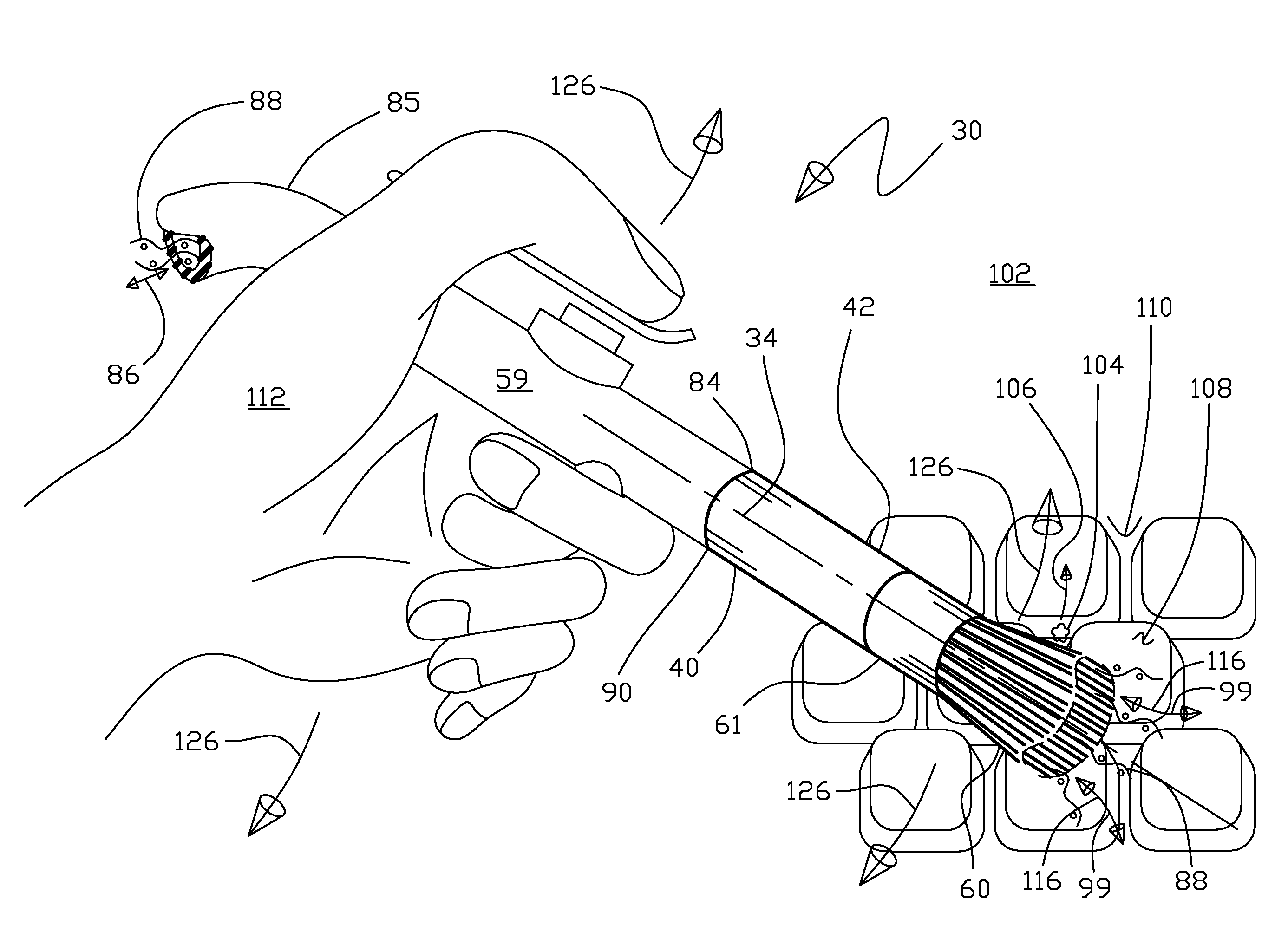
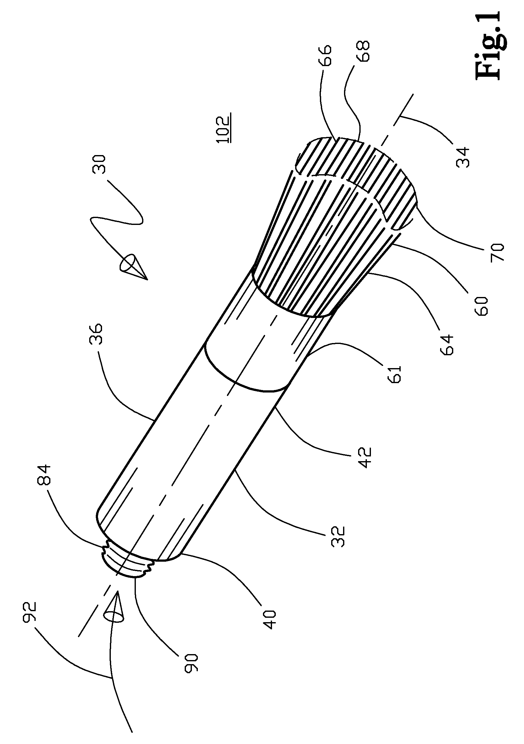
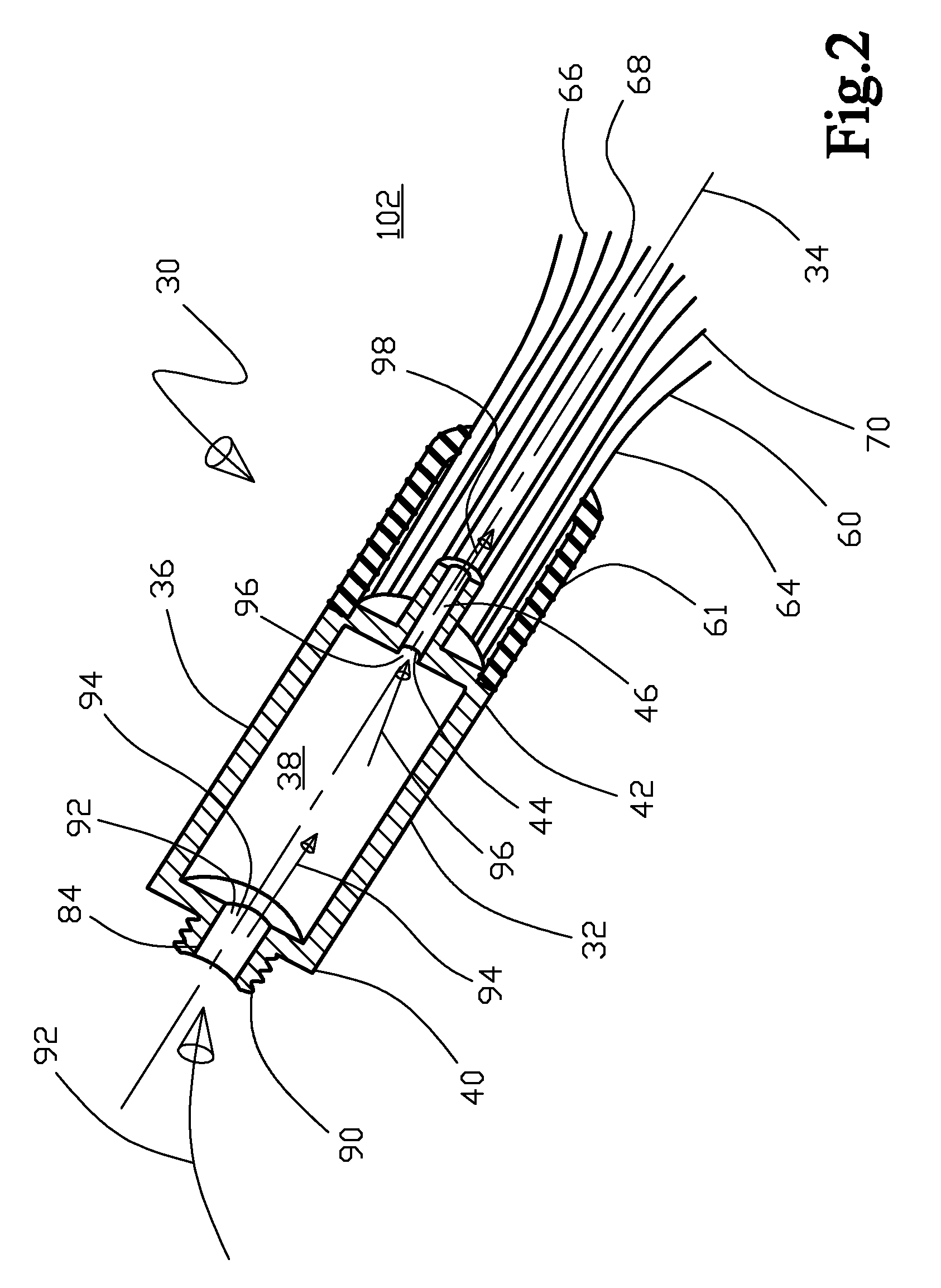
[0033]With initial reference to FIG. 1 shown is a perspective view of the fluid cleaning apparatus 30, FIG. 2 is a perspective cross sectional view of the fluid cleaning apparatus 30, and FIG. 3 is a perspective view of the fluid cleaning apparatus 30 with a plurality of brush 64 bristles 66 having free tip portions 68 that form a brush opening 70 that includes two oppositely disposed concave sections 74 and two oppositely disposed convex sections 76 that form a continuously curved perimeter 72. Continuing, FIG 4 is an exploded perspective view of an alternative embodiment of the fluid cleaning apparatus 130, FIG. 5 is an exploded perspective cross sectional view of an alternative embodiment of the fluid cleaning apparatus 130, and FIG. 6 is an exploded perspective cross sectional view of the distal end portion 42 or 142, the aperture 44 or 144, and the agitation element 60 in the form of the plurality of brush 64 bristles 66 with the selected fluid shown 88. Further continuing, FIG...


PUM


Abstract

A fluid cleaning apparatus and method for use with a fluid interface that has structure for creating a fluid flowrate of a selected fluid, wherein the apparatus includes a housing that has a surrounding side wall about a longitudinal axis, the sidewall defining an interior between proximal end and distal end portions. The proximal end portion removably engages the fluid interface with fluid communication between the interior and the structure for creating the selected fluid's flowrate, the distal end portion including an aperture that is in fluid communication with the interior. Also included with the apparatus is an agitation element that is disposed adjacent to the distal end portion such that the aperture is in fluid communication with the agitation element and an external environment, wherein operationally the agitation element helps to dislodge a particulate from a selected surface in conjunction with the selected fluid to clean the selected surface.

Description

TECHNICAL FIELD [0001]The present invention generally relates to a fluid cleaning apparatus and more particularly to a portable manually operated fluid cleaning apparatus that includes an agitation element for the cleaning of selected difficult to reach areas / surfaces such as a convoluted surface on a desired item.BACKGROUND OF INVENTION[0002]There are a variety of fluid cleaning apparatus in the prior art. A fluid cleaning apparatus system typically includes: a fluid reservoir, a means for generating fluid movement, a means for regulating fluid flow, and an agitation element that is adjacent to a fluid discharge / intake nozzle. The reservoir contains a fluid and usually also has a means for motivating the fluid to communicate into the means for regulating the fluid flow and further communicating to the fluid nozzle and finally to the agitation element. The fluid can be a liquid or a gas or even a combination of a liquid and a gas wherein the reservoir and means for motivating the fl...

Claims


Application Information

Patent Timeline
IPC IPC(8): B08B7/00
CPCA46B11/063A46B15/00A46B15/0051A46B15/0053B08B3/04A47L5/02A47L9/0693A47L9/08B08B1/00A46B2200/3026
Inventor HENDERSON, JOHN ROBERT
Owner HENDERSON JOHN ROBERT
Learn More