Reinforcement element for the securing of a mixing valve to a mounting rail

Active Publication Date: 2019-04-18
J VAN WALRAVEN
4 Cites 0 Cited by

AI-Extracted Technical Summary

Problems solved by technology

However, such a connection between the mixing valve and the m...

Benefits of technology

[0008]By having a first use mode and a second use mode, in which effectively different sides of the reinforcement element are used, this compatibility with as much embodiments (brands) of mixing valves as possible is further increased.
[0009]With respect to the plate halves, the bottom plate lies recessed from and parallel to the common plane of said plate halves. That is, there is a height difference between the plate halves and the bottom plate. In the first use...

Abstract

A reinforcement element includes a mounting plate with two plate halves spaced apart by a centre portion. In a first use mode, the reinforcement element is secured onto a mounting rail. The centre portion of the reinforcement element engages the mounting rail, and a mixing valve is secured to the mounting plate via a pattern front face mixing valve securing holes. A body of the mixing valve is at least partially supported by the plate halves of the mounting plate. In a second use mode, the mixing valve is secured to the reinforcement element via a pattern back face mixing valve securing holes, while the bottom plate of the centre portion at least partially engages and supports a body of the mixing valve.

Application Domain

Technology Topic

Image

  • Reinforcement element for the securing of a mixing valve to a mounting rail
  • Reinforcement element for the securing of a mixing valve to a mounting rail
  • Reinforcement element for the securing of a mixing valve to a mounting rail

Examples

  • Experimental program(1)

Example

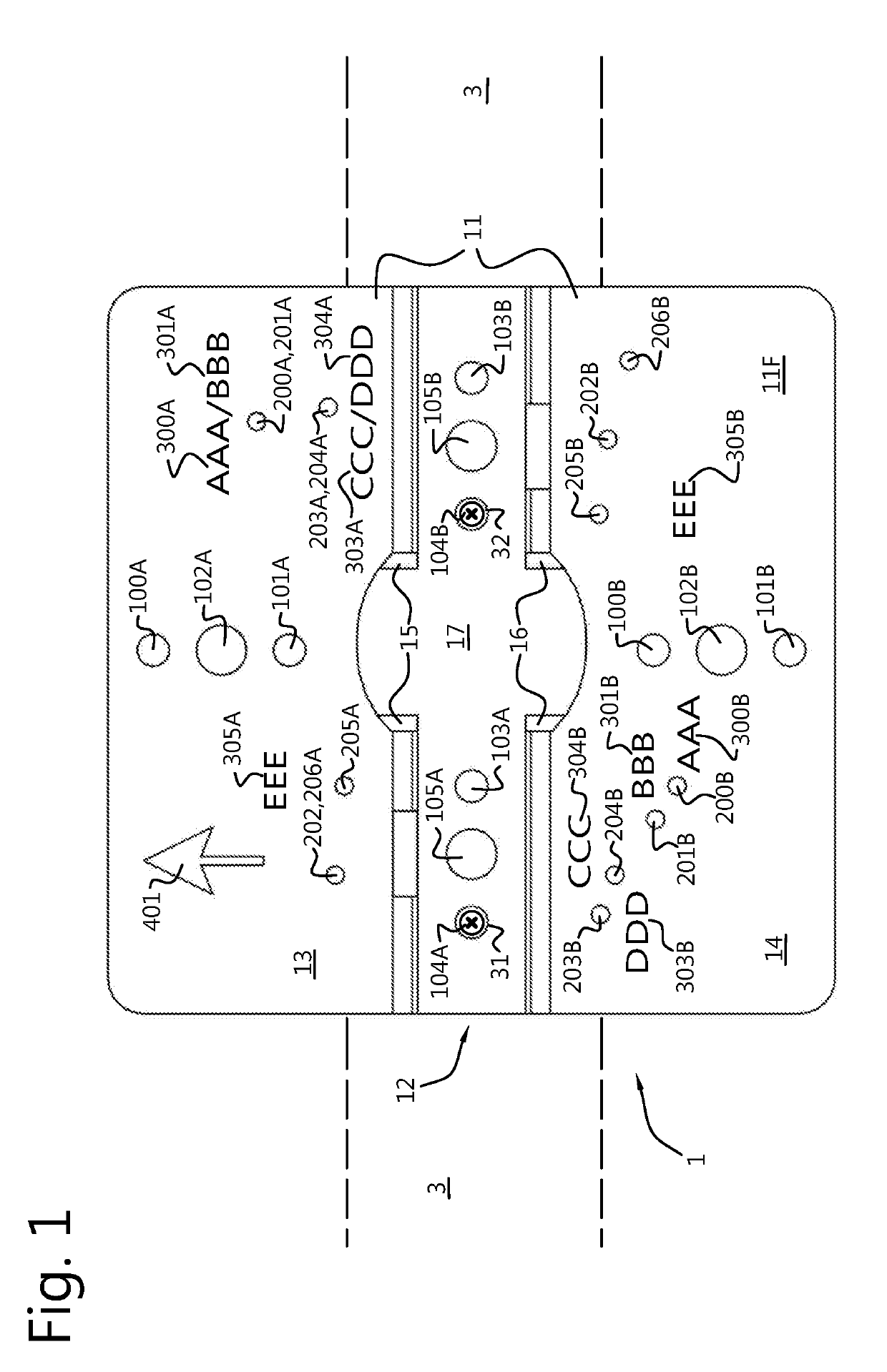
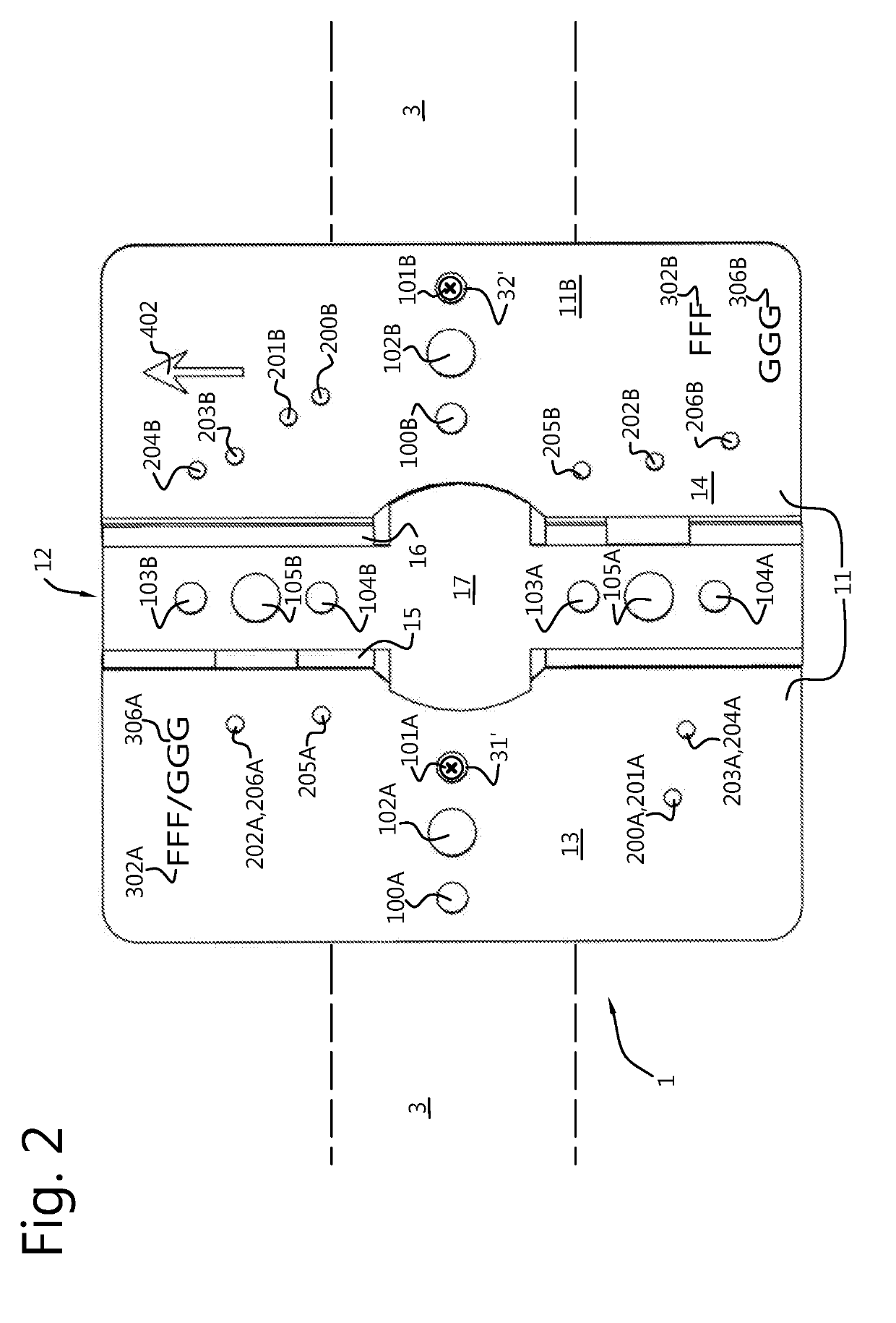
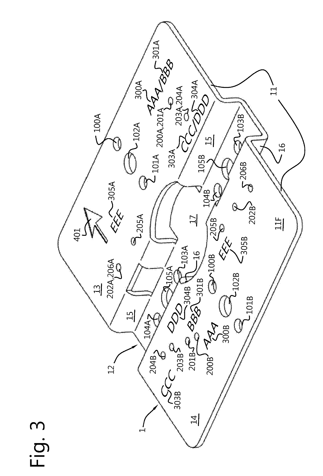
[0035]With reference to FIGS. 1-3, a reinforcement element 1 for the securing of a mixing valve, e.g. a shower valve, to a mounting rail 3 is shown. FIG. 1 shows a front view of said reinforcement element 1, FIG. 2 shows a rear view of the reinforcement element 1, and FIG. 3 shows an isometric view from a front face 11F of the reinforcement element 1.
[0036]The reinforcement element 1 comprises a mounting plate 11 that comprises a first plate half 13 and a second plate half 14 which are spaced apart by a centre portion 12 and are generally arranged in a common plane. The plane spanned by the first plate half 13 may be inclined about an absolute value of up to 30 degrees with respect to the plane spanned by the second plate half 14. In other words, the first plate half 13 and the second plate half 14 may extend at angles of between 150 degrees and 210 degrees with respect to each other. Preferably, the plate halves 13, 14 extend at an angle of approximately 180 degrees with respect to each other.
[0037]The first 13 and second 14 halves of the mounting plate 11 have a front face 11F, shown in FIGS. 1 and 3, and a back face 11B, shown in FIG. 2, opposite the front face 11F, the back face 11B being the face from which the centre portion 12 projects. The front face 11F of the mounting plate 11 is the face with respect to which the centre portion 12 is arranged recessed, or rearwards/aft, of the plate halves 13, 14, while the back face 11B of the mounting plate 11 is the face with respect to which the centre portion 12 is arranged projecting, or in front, of the plate halves 13, 14.
[0038]The centre portion 12 comprises two flanges 15, 16 and a bottom plate 17 connected to an end of the flanges 15, 16, wherein the bottom plate 17 may be arranged substantially perpendicular with respect to the flanges 15, 16. Each of the flanges 15, 16 is connected to a respective plate half 13, 14 of the mounting plate 11 with an end remote from the bottom plate 17, wherein the bottom plate 17 is arranged substantially parallel to the common plane of the first plate half 13 and the second plate half 14, and lies recessed from said plane. The bottom plate 17 is displaced with respect to said plane in a direction perpendicular thereto. The plane spanned by the bottom plate 17 may be inclined at an absolute value of up to 30 degrees with respect to the plane spanned by the first plate half 13 and/or the second plate half 14. One may say that the centre portion 12, i.e. the flanges 15, 16 and the bottom plate 17, form a gutter with respect to the mounting plate 11, as is visible most clearly in FIG. 3.
[0039]As is visible in FIGS. 1-3, the reinforcement element 1 has a pattern of holes. The pattern of holes includes reinforcement element securing holes 100A, 100B, 101A, 101B, 102A, 102B, 103A, 103B, 104A, 104B, 105A, 105B, that allow the reinforcement element 1 to be secured onto the mounting rail 3, and mixing valve securing holes 200A, 200B, 201A, 201B, 202A, 202B, 203A, 203B, 204A, 204B, 205A, 205B, 206A, 206B, that allow a particular mixing valve to be secured onto the reinforcement element 1 in a predefined manner.
[0040]In the shown embodiment, the reinforcement element has six patterns 100, 101, 102, 103, 104, 105 of reinforcement element securing holes, wherein each pattern is defined by a pair of holes, and wherein each hole of a pair is respectively marked A or B. That is, the first pair of reinforcement element securing holes is indicated by reference numerals 100A and 100B, etc. It is however conceived that a pattern of reinforcement element securing holes may be defined by more (e.g. three holes or more), or less (e.g. a single hole) holes.
[0041]More specifically, the patterns of reinforcement element securing holes 100A, 100B, 101A, 101B, 102A, 102B, 103A, 103B, 104A, 104B, 105A, 105B include three, i.e. at least one, patterns of front face reinforcement element securing holes 103A, 103B, 104A, 104B, 105A, 105B, suited for use when the front face 11F of the mounting plate 11 faces away from the mounting rail 3, and three, i.e. at least one, patterns of back face reinforcement element securing holes 100A, 100B, 101A, 101B, 102A, 102B, suited for use when the back face 11B of the mounting plate 11 faces away from the mounting rail 3.
[0042]The front face reinforcement element securing holes 103A, 103B, 104A, 104B, 105A, 105B are here arranged in the bottom plate 17 of the centre portion 12, while the back face reinforcement element securing holes 100A, 100B, 101A, 101B, 102A, 102B are arranged in the plate halves 13, 14 of the mounting plate 11.
[0043]As may be observed from FIGS. 1-3, some of the reinforcement element securing holes may be larger than other reinforcement element securing holes. More in particular, reinforcement element securing holes 102A, 102B, 105A and 105B have a larger diameter than reinforcement element securing holes 100A, 100B, 101A, 101B, 103A, 103B, 104A and 104B. For example, the reinforcement element securing holes having a smaller diameter may allow the securing of the reinforcement element onto the mounting rail with screws, while the reinforcement element securing holes having a larger diameter may allow the securing of the reinforcement element onto the mounting rail with a threaded rod that extends from the rail towards the reinforcement element and a nut that is threaded onto the threaded rod. A threaded body of a screw is typically smaller in diameter than a threaded rod on which a nut is threaded, hence the difference in hole diameter.
[0044]The mixing valve securing holes include at least at least a first 200A, 200B, a second 201A,
[0045]201B, and a third 202A, 202B pattern of mixing valve securing holes such that the reinforcement element 1 can be mated with at least three different embodiments (brands) of mixing valves. Here, the reinforcement element 1 has seven mutually different patterns of mixing valve securing holes, such that the reinforcement element 1 can be mated with seven different embodiments (brands) of mixing valves.
[0046]Some of the mixing valve securing holes are suited for use when the front face 11F of the mounting plate 11 faces away from the mounting rail 3. These holes are defined as front face mixing valve securing holes 200A, 200B, 201A, 201B, 203A, 203B, 204A, 204B, 205A, 205B. The embodiments of FIGS. 1-3 include five mutually different patterns of such front face mixing valve securing holes 200A, 200B, 201A, 201B, 203A, 203B, 204A, 204B, 205A, 205B, here all arranged in the mounting plate 11 of the reinforcement element 1.
[0047]Other mixing valve securing holes are suited for use when the back face 11B of the mounting plate 11 faces away from the mounting rail 3. These holes are defined as back face mixing valve securing holes 202A, 202B, 206A, 206B. The embodiments of FIGS. 1-3 include two mutually different patterns of such back face mixing valve securing holes 202A, 202B, 206A, 206B, here all arranged in the mounting plate 11 of the reinforcement element 1.
[0048]One particular mixing valve securing hole, in the shown embodiment, is either a front face mixing valve securing hole, only suited for use when the front face of the mounting plate faces away from the rail, or a back face mixing valve securing hole, only suited for use when the back face of the mounting plate faces away from the rail. However, embodiments are conceived, and within the scope of the invention, wherein a particular hole, or particular holes, are both suited for use when the front face of the mounting plate faces away from the rail as well as when the back face of the mounting plate faces away from the rail.
[0049]One particular hole, in the shown embodiment, is either a mixing valve securing hole, only suited to mount a mixing valve to the reinforcement element, or a reinforcement element securing hole, only suited to mount the reinforcement element to the mounting rail. That is, the mixing valve securing holes 200A, 200B, 201A, 201B, 202A, 202B, 203A, 203B, 204A, 204B, 205A, 205B, 206A, 206B and the reinforcement element securing holes 100A, 100B, 101A, 101B, 102A, 102B, 103A, 103B, 104A, 104B, 105A, 105B are mutually different holes. However, embodiments are conceived, and within the scope of the invention, where a particular hole, or particular holes, are both suited to mount a mixing valve to the reinforcement element as well as to mount the reinforcement element to the mounting rail, depending on the particular application of the reinforcement element and the embodiment of mixing vale used.
[0050]It is noted that, in the present embodiment, each pattern of mixing valve securing holes 200A, 200B, 201A, 201B, 202A, 202B, 203A, 203B, 204A, 204B, 205A, 205B, 206A, 206B includes two holes, each hole of a pair respectively being marked A or B. That is, the first pair of mixing valve securing holes is indicated by reference numerals 200A and 200B, etc. It is however conceived that a pattern of mixing valve securing holes may be defined by more (e.g. three holes or more), or less (e.g. a single hole) holes.
[0051]Further visible in FIGS. 1-3 is that some of the mixing valve securing holes form a part of multiple, here two, patterns of mixing valve securing holes. More specifically, hole 200A, 201A forms a part of both the first pattern 200 and the second pattern 201 of mixing valve securing holes; hole 203A, 204A forms a part of both the third pattern 203 and the fourth pattern 204 of mixing valve securing holes; and hole 202A, 206A forms a part of both the second pattern 202 and the sixth pattern 206 of mixing valve securing holes.
[0052]The reinforcement element 1 has a first use mode and a second use mode.
[0053]In the first use mode, the reinforcement element 1 is secured onto the mounting rail via one of the patterns of the reinforcement element securing holes 100A, 100B, 101A, 101B, 102A, 102B, 103A, 103B, 104A, 104B, 105A, 105B, the centre portion 12, here the bottom plate 17 of the centre portion 12, engaging the mounting rail 3, the front face 11F facing away from the mounting rail 3, and the mixing valve (not shown) being secured to the mounting plate 11 via a pattern of the front face mixing valve securing holes 200A, 200B, 201A, 201B, 203A, 203B, 204A, 204B, 205A, 205B, and a body of the mixing valve is at least partially supported by the plate halves 13, 14 of the mounting plate 11.
[0054]In the shown embodiment, the reinforcement element 1 is secured onto the mounting rail with screws 31, 32 via a pattern of the front face reinforcement element securing holes 104A, 104B in the first use mode.
[0055]In the shown embodiment, a space may be present between the plate halves 13, 14 of the mounting plate 11 and the mounting rail 3.
[0056]In the shown embodiment, in the first use mode thereof, the longitudinal axis of the centre portion 12 is aligned parallel to the mounting rail 3.
[0057]In the second use mode, the reinforcement element 1 is secured onto the mounting rail 3 via one of the patterns of the reinforcement element securing holes 100A, 100B, 101A, 101B, 102A, 102B, 103A, 103B, 104A, 104B, 105A, 105B, the plate halves 13, 14 of the mounting plate 11 at least partially engaging the mounting rail 3, the back face 11B facing away from the mounting rail 3, and the mixing valve (not shown) being secured to the reinforcement element 1 via one of the patterns of the back face mixing valve securing holes 202A, 202B, 206A, 206B, while the bottom plate 17 of the centre portion 12 at least partially engages and supports a body of the mixing valve.
[0058]More specifically, with reference to FIG. 2, the reinforcement element 1 is secured onto the mounting rail 3 with screws 31′, 32′ via a pattern of the back face reinforcement element securing holes 101A, 101B in the second use mode.
[0059]In the shown embodiment, a space may be present between the bottom plate 17 of the centre portion 12 and the mounting rail 3.
[0060]In the shown embodiment, in the second use mode thereof, the longitudinal axis of the centre portion 12 is arranged at an angle of from 70° to 110°, e.g. substantially perpendicular, to the longitudinal axis of the mounting rail 3.
[0061]Comparing FIG. 1 to FIG. 2, it may be observed that, in the second use mode, the reinforcement element 1 is oriented with respect to an axis perpendicular to the common plane of the plate halves 13, 14 at an angle of from 80° to 100° compared to the first use mode.
[0062]It is noted that, to secure a particular embodiment of mixing valve onto the reinforcement element 1, only one pattern of the at least three patterns of mixing valve securing holes 200A, 200B, 201A, 201B, 202A, 202B, 203A, 203B, 204A, 204B, 205A, 205B, 206A, 206B is used, and that either the first use mode or the second use mode of the reinforcement element 1 is used.
[0063]Visible in FIGS. 1-3 are mixing valve indication marks 300A, 300B, 301A, 301B, 302A, 302B, 303A, 303B, 304A, 304B, 305A, 305B, 306A, 306B, provided near the mixing valve securing holes 200A, 200B, 201A, 201B, 202A, 202B, 203A, 203B, 204A, 204B, 205A, 205B, 206A, 206B. Different mixing valve indication marks may be provided to distinguish the mounting positions of different embodiments (brands) of mixing valves from each other.
[0064]Visible in FIGS. 1-3 are orientation indication marks 401, 402, are provided on the plate halves 13, 14 of the mounting plate 11. The indication marks 401, 402 may be provided to indicate the mounting orientation of the face, i.e. the back face 11B or the front face 11F, they are applied on.
[0065]With reference to FIGS. 4-7, a method for the installation of a mixing valve 2 to a mounting rail 3 is shown, the method comprising the steps of: [0066] securing the reinforcement element 1 onto the mounting rail 3 by providing one or more male fastening elements 31, 32 that extend through a pattern of the reinforcement element securing holes 100A, 100B, 101A, 101B, 102A, 102B, 103A, 103B, 104A, 104B, 105A, 105B and into the mounting rail 3; [0067] securing the mixing valve 2 onto the reinforcement element 1 by providing one or more male fastening elements 33, 34 that extend through a pattern of the mixing valve securing holes 200A, 200B, 201A, 201B, 202A, 202B, 203A, 203B, 204A, 204B, 205A, 205B, 206A, 206B and into the mounting rail 3.
[0068]As stated before, the mixing valve 2 may be a mixing valve of a shower and is of the type that receives at least three, here four, conduits. Such mixing valves are typically installed behind a false wall, while a frame is arranged behind said false wall, the frame supporting the mixing valve.
[0069]With reference to FIG. 4, two columns 410, 420 are shown that constitute end parts of such a frame.
[0070]With reference to FIG. 5, rails 510, 520, 530 are mounted in between said columns 410, 420. In the present embodiment, the rails 510, 520, 530 are telescopic rails that can easily be elongated and shortened, but this is merely a non-limiting example of a rail. In a more simple embodiment, a length of wood, e.g. a wooden plank of a length matching the distance between the columns 410, 420 may be installed between the columns 410, 420. Installed on the rails 510, 520, 530 are pipe clamps 540-545.
[0071]In presently known installations, a mixing valve is often directly mounted to rail 530.
[0072]As is more clearly visible in FIG. 5A, which shows a more detailed view of the reinforcement element 1 being mounted to rail 530, according to the invention, a reinforcement element 1 is further secured on the mounting rail 530, here in a first use mode thereof, with a longitudinal axis of the centre portion being parallel to the mounting rail 530 and the bottom plate 17 of the centre portion 12 contacting the mounting rail 530. The reinforcement element 1 is secured onto the mounting rail 530 with two screws 31, 32 that extend through the fourth pattern of reinforcement element securing holes 103A, 103B and that grip into the mounting rail 530.
[0073]With reference to FIG. 6, the same elements as in FIG. 5 are shown, and are numbered accordingly. Further visible in FIG. 6 is a mixing valve 2, secured onto the reinforcement element 1.
[0074]As is more clearly visible in FIG. 6A, which shows a more detailed view of the mixing valve 2 and the reinforcement valve 1 being mounted to the rail 530, the mixing valve 2 is secured to the reinforcement element 1 by screwing two screws 33, 34 into the mounting rail 530 through the fifth pattern of mixing valve securing holes 204A, 204B.
[0075]As can be seen, the body of the mixing valve 2, near pipe receiving ends 22, 23, may partially be received between the flanges of the centre portion.
[0076]In FIGS. 6 and 6A, one embodiment of a mixing valve 2 is shown, that is secured through the fifth pattern of mixing valve securing holes 204A, 204B. It will be understood that if another embodiment of a mixing valve is used, it may be installed through another pattern of mixing valve securing holes.
[0077]The mixing valve 2 shown in FIGS. 6 and 6A is of the type that is able to receive four conduits at receiving ends 21, 22, 23, 24 thereof. Shown in FIG. 7 are three conduits 4A, 4B, 4C that are received by the receiving ends 21, 22, 23 of the mixing valve 2. The conduits 4A, 4B, 4C are further supported by the pipe clamps 540-545.
[0078]It is noted that, after the mixing valve 2 is installed, the space behind the rails 510, 520, 530 is essentially free of components related to the securing of the mixing valve 2 onto the rail 530.

PUM

no PUM

Description & Claims & Application Information

We can also present the details of the Description, Claims and Application information to help users get a comprehensive understanding of the technical details of the patent, such as background art, summary of invention, brief description of drawings, description of embodiments, and other original content. On the other hand, users can also determine the specific scope of protection of the technology through the list of claims; as well as understand the changes in the life cycle of the technology with the presentation of the patent timeline. Login to view more.

Similar technology patents

Vehicle door frame sealing strip structure and automobile

PendingCN114789647AIncrease compatibilityImprove appearance performanceEngine sealsVehicle sealing arrangementsLap jointCar door
Owner:阿维塔科技(重庆)有限公司

Cell phone reading mode using image timer

InactiveUS20130248604A1Increase speed and efficiencyIncrease compatibilityPayment architectureSpecial data processing applicationsImage captureVideo camera
Owner:HONEYWELL INT INC

Rust-proof gate valve with high sealing performance

PendingCN113606357ANot easy to slideIncrease compatibilitySpindle sealingsPlug valvesEngineeringGate valve
Owner:铜陵荣景科技有限公司

Fully-automatic pipette suction tip filling machine

Owner:上海括羽智能科技有限公司

Classification and recommendation of technical efficacy words

Why Eureka
Try Eureka