Sound source separation method and sound source separation apparatus

a technology of sound source separation and sound source, applied in the field of sound source separation, can solve the problems of low sound source separation performance for audio signals or the like, and achieve the effect of high separation performan

Active Publication Date: 2019-04-18
HITACHI LTD
View PDF2 Cites 8 Cited by
  • Summary
  • Abstract
  • Description
  • Claims
  • Application Information

AI Technical Summary

Benefits of technology

[0010]According to the present invention, it is possible to provide the sound source separat

Problems solved by technology

However, with the modeling by using NMF, since the high-order correlation among the neighborhood frequencies which the audio signal or the like has cannot be utilized, there i

Method used


Image

  • Sound source separation method and sound source separation apparatus
  • Sound source separation method and sound source separation apparatus
  • Sound source separation method and sound source separation apparatus

Examples


first embodiment

[0063]A sound source separation apparatus 100 according to the first embodiment of the present invention will be described with respect to FIGS. 5 to 7. FIG. 5 is a block diagram exemplifying a functional configuration of the sound source separation apparatus according to the first embodiment of the present invention. The sound source separation apparatus 100 is provided with a band division determining portion 101, a time-frequency domain transforming portion 110, a sound source state updating portion 120, a model parameter updating portion 130, a time-frequency domain separated sound calculating portion 140, a time domain transforming portion 150, and a sound source state outputting portion 160. Here, the model parameter updating portion 130 is configured to include a mixture weight updating portion 131, an NMF parameter updating portion 132, and a separation filter updating portion 133.

[0064]FIG. 6 is a block diagram depicting a hardware configuration of the sound source separati...

second embodiment

[0100]A sound source separation apparatus 300 according to the second embodiment of the present invention will now be described with reference to FIGS. 8 and 9. The sound source separation apparatus 300 of the second embodiment has the same configuration as that of the sound source separation apparatus 100 of the first embodiment depicted in FIG. 5 except that a sound source state correcting portion 320 in FIG. 8 is added. Therefore, in the following, only the sound source state correcting portion 320 will be described, and a description of any of other portions is omitted here.

[0101]In addition, a processing flow of the second embodiment depicted in FIG. 9 is also the same as that of the first embodiment depicted in FIG. 7 except that correction (Step S400) of the sound source state (posterior probability) is added. Therefore, in the following, only the correction (Step S400) of the sound source state (posterior probability) will be described, and a description of any of other port...


PUM


Abstract

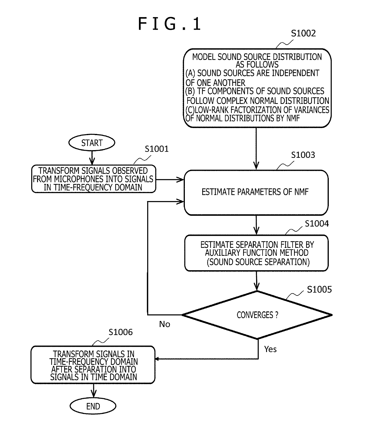
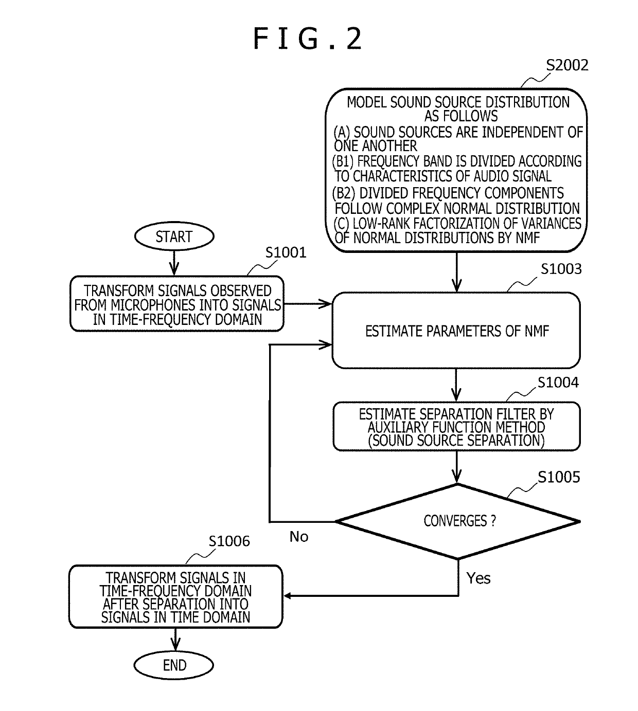
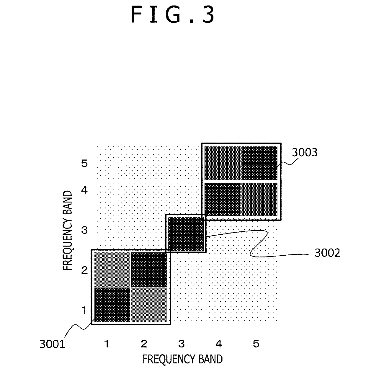
There is provided a sound source separation method of carrying out sound source separation of an audio signal inputted from an input device by using a modeled sound source distribution, by an information processing apparatus provided with a processing device, a storage device, the input device, and an output device. In this method, as a condition followed by the model, sound sources are independent of one another, powers which the sound sources have are modeled for each of frequency bands obtained through band division, a relationship among the powers for the frequency bands different from each other is modeled by nonnegative matrix factorization, and components obtained through the division of the sound source follow a complex normal distribution.

Description

BACKGROUND OF THE INVENTION1. Field of the Invention[0001]The present invention relates to a technology pertaining to sound source separation, and more particularly to a sound source separation method and a sound source separation apparatus each of which has high separation performance.2. Description of the Related Art[0002]A blind sound source separation technology means a signal processing technology for estimating individual original signals before mixture, under a situation in which information associated with a sound source mixing process or the like is unknown, from only an observed signal obtained through mixture of sound source signals from a plurality of sound sources. In recent years, the research of an overdetermined blind sound source separation technology for carrying out sound source separation under a condition in which the number of microphones is equal to or larger than the number of sound sources has been actively progressed.[0003]“The independent component analysi...

Claims


Application Information

Patent Timeline
IPC IPC(8): G10L21/0308G10L21/0388
CPCG10L21/0308G10L21/0388
Inventor IKESHITA, RINTAROKAWAGUCHI, YOHEI
Owner HITACHI LTD
Why Eureka
Try Eureka