Automatic toroidal core winding machine

a winding machine and toroidal core technology, applied in the direction of transformer/inductance details, inductances with magnetic cores, inductances, etc., can solve the problems of high labor cost, low efficiency of toroidal core winding method, and large limitation of machine machining range, so as to improve production efficiency, reduce restriction and effect on winding quality

Active Publication Date: 2019-04-18
ZHONGSHAN COMPETENT AUTOMATION EQUIP CO LTD
View PDF0 Cites 10 Cited by
  • Summary
  • Abstract
  • Description
  • Claims
  • Application Information

AI Technical Summary

Benefits of technology

[0022]The present invention achieves automation from wire delivery, feeding, shuttle (namely as a wire storage ring) opening to wire hanging, wire winding, wire cutting and product taking with significantly improved production efficiency, reduced restriction and effect on the quality of winding both from manual proficiency.
[0023]According to the present invention, when the excessive waste wire needs to be reclaimed after completing the winding of a toroidal core, the wire can be reclaimed without forcibly opening the shuttle. The excessive wire is winded around the toroidal core and the wire hooking rod into a ring form, and then the wire is cut by the pneumatic scissors to open the ring, the excessive wire can be reclaimed after the wire is cut at the end of the toroidal core. Automatic operation of collecting waste wire on the shuttle is achieved according to the present invention with high efficiency and high speed. Thus, the service life of the shuttle is improved and the current situation of the existing machine being operated annually is changed.

Problems solved by technology

However, it can only be used for a toroidal core having a great inner diameter, and only one type of wire can be winded around the toroidal core, which limits the machining range of the machine to a large extent.
Such a toroidal core winding method is extremely low in efficiency and high in labor cost.

Method used


Image

  • Automatic toroidal core winding machine
  • Automatic toroidal core winding machine
  • Automatic toroidal core winding machine

Examples


Embodiment Construction

[0046]The present invention will be further described below in detail in combination with the accompanying drawings.

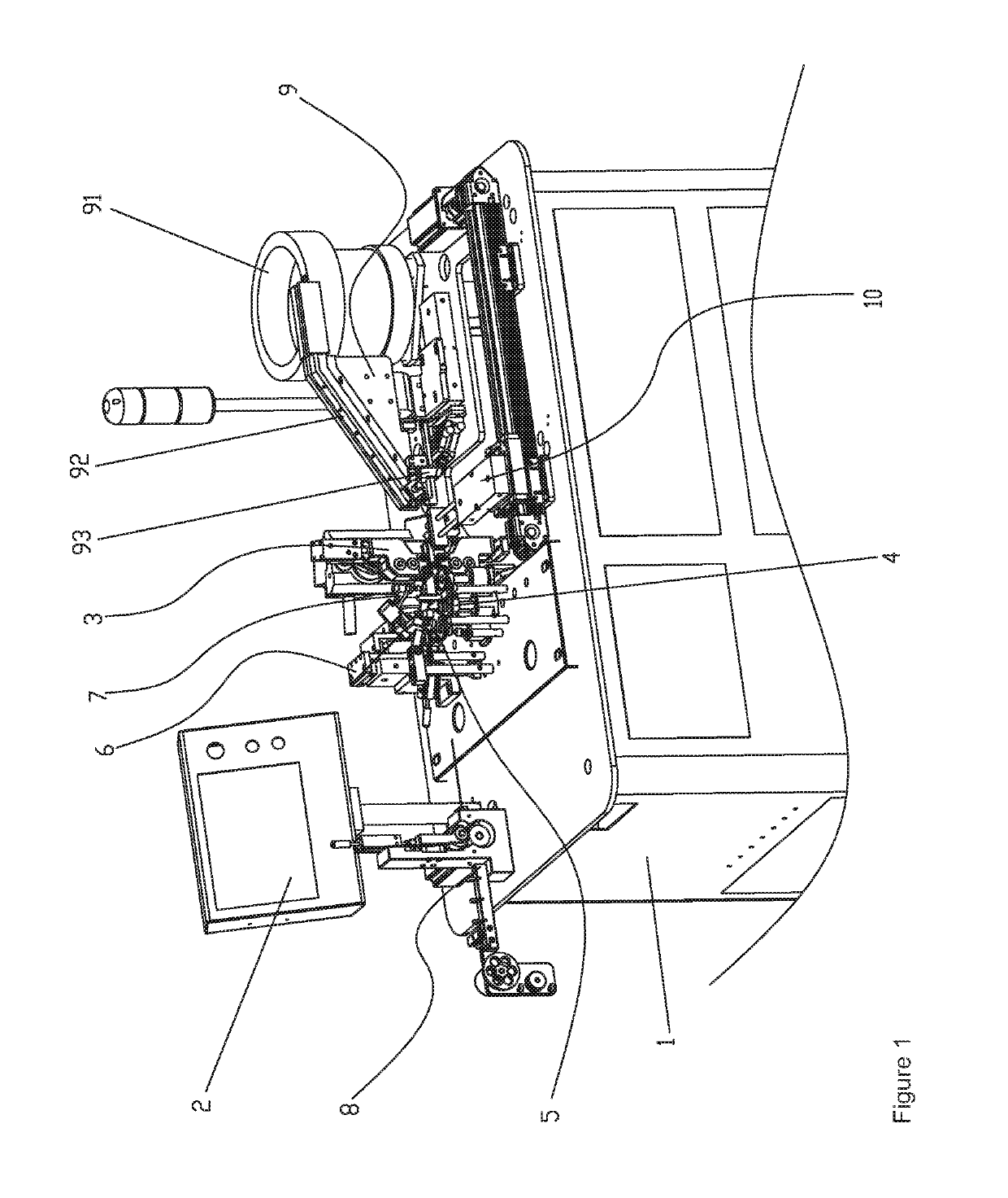
[0047]As illustrated in the FIG. 1 to FIG. 17, an automatic toroidal core winding machine includes:

[0048]a frame 1 configured for installing of various mechanisms thereon;

[0049]a control device 2 disposed on the frame 1 and configured to control operation of each mechanism / device;

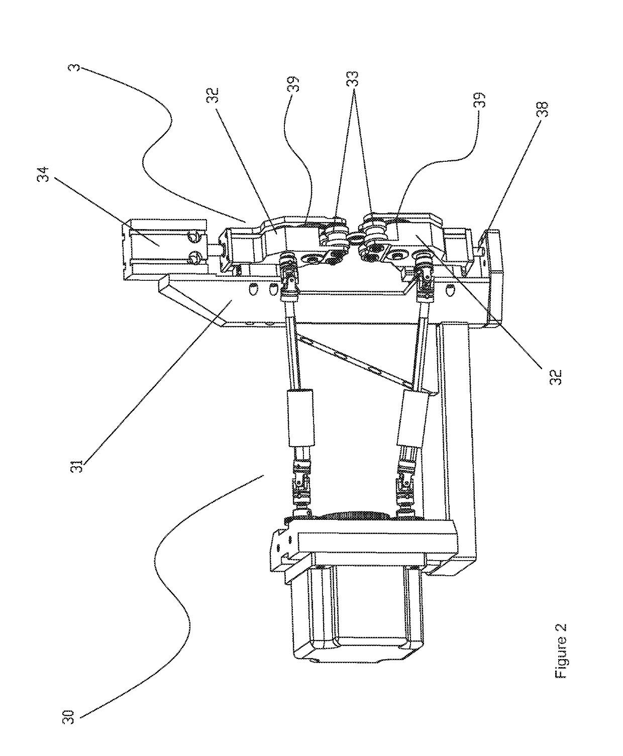
[0050]a clamping and wire arranging mechanism 3 disposed on the frame 1 and configured to clamp and rotate a toroidal core to be winded with a wire;

[0051]a winding mechanism, comprising a shuttle 4 having a ring opening 41 and a driving device 5 for supporting and driving the shuttle 4 to rotate, the shuttle 4 is provided with a slider 42 and a wire storage and hooking aperture 43, and the frame 1 is provided with a wire hanging device 6 for hanging the wire allowing the shuttle 4 to store the wire and to wind the wire respectively;

[0052]a detecting and positioning mechanism 7 disposed around ...


PUM

PropertyMeasurementUnit
included angleaaaaaaaaaa
inner diameteraaaaaaaaaa
speedaaaaaaaaaa

Abstract

An automatic toroidal core winding machine, including: a frame, control device, clamping and wire arranging mechanism, winding mechanism, wire delivering mechanism, feeding mechanism, automatic stripping mechanism and wire reclaiming device for reclaiming excessive wires around the shuttle, the winding mechanism including a shuttle and driving device for supporting and driving the shuttle to rotate, the shuttle includes a slider and wire storage and hooking aperture, and the frame includes a detecting and positioning mechanism used for positioning the ring opening, the slider and the wire storage and hooking aperture of the shuttle, and a wire hanging device for hanging the wire allowing the shuttle to store and wind the wire. The machine achieves automation from wire delivery, feeding, shuttle opening to wire hanging, wire winding, wire cutting, product taking and wire reclaiming with significantly improved production efficiency, reduced restriction and effect on the quality of winding from manual proficiency.

Description

FIELD OF THE INVENTION[0001]The present invention relates to an automatic toroidal core winding machine, belongs to the technical field of winding equipment for toroidal coil.BACKGROUND OF THE INVENTION[0002]Electromagnetic assembly is widely applied to various fields, and the electromagnetic assemblies are inevitably often used in different types of electronic products, therefore, their production quality is closely related to the service life and quality of the electronic products. Toroidal inductance coils are more extensively used in electromagnetic assemblies, and the existing winding machine on the market generally comprises a wire releaser, a wire delivering assembly, a winding assembly, a feeder and a hopper. A wire is delivered to the winding assembly from the wire releaser, and a toroidal core is placed into the hopper capable of vibrating and fed to a winding working position by the feeder, then, two pairs of inclined wheel sets and winding needles of the winding assembly...

Claims


Application Information

Patent Timeline
Patent Type & Authority Applications(United States)
IPC IPC(8): H01F17/06H01F41/082H01F41/096H01F27/30
CPCH01F17/062H01F41/082H01F41/096H01F27/306H01F41/08H01F41/06
Inventor ZHOU, KECHEN, HUILIAO, SHUYANMA, XIYANHUANG, QIHANLIU, PENGXIONG, GANG
Owner ZHONGSHAN COMPETENT AUTOMATION EQUIP CO LTD
Why Eureka
Try Eureka