
Substrate supporting member and substrate processing apparatus including same

a substrate and supporting member technology, applied in the direction of coatings, chemical vapor deposition coatings, electric discharge tubes, etc., can solve the problems of increasing the amount of heat transfer gas remaining after the completion affecting the productivity of the substrate processing process, and unwanted arcing inside the heat transfer gas flow path, so as to minimize the time

Inactive Publication Date: 2019-04-18
SEMES CO LTD
View PDF0 Cites 0 Cited by
  • Summary
  • Abstract
  • Description
  • Claims
  • Application Information

AI Technical Summary

Benefits of technology

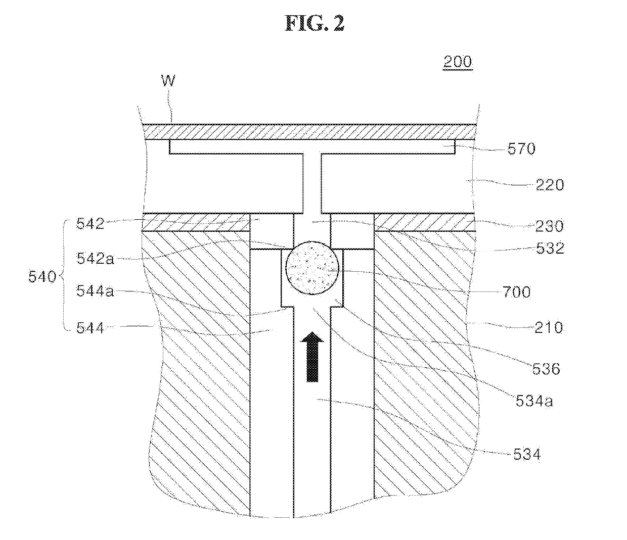
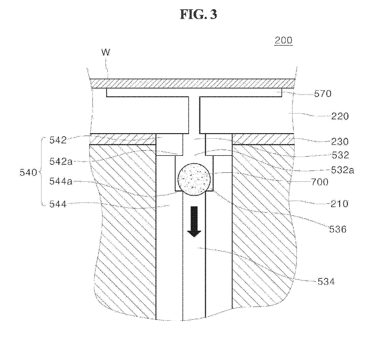
The present invention provides a substrate supporting member and a substrate processing apparatus that can minimize arcing while exhausting heat transfer gas. The gas flow path is designed with a movable gas flow restricting member that allows for smoother gas flow compared to supplying gas through the path. A penetrating flow path is also provided to facilitate smoother gas flow in case the gas flow restricting member blocks the lower opening. The gas flow restricting member is placed within the gas flow path to restrict the gas flow in different directions, resulting in faster heat transfer while preventing arcing.

Problems solved by technology

Meanwhile, in the case of a substrate processing apparatus using plasma for substrate processing, unwanted arcing may occur inside the heat transfer gas flow path of the substrate supporting member due to a high frequency power applied for plasma generation.
However, since the conductance of the gas flow path is reduced according to this method as a result, the time required for exhausting the remaining heat transfer gas after completion of the substrate processing process is increased, thereby deteriorating the productivity.

Method used


Image

  • Substrate supporting member and substrate processing apparatus including same
  • Substrate supporting member and substrate processing apparatus including same
  • Substrate supporting member and substrate processing apparatus including same

Examples


Embodiment Construction

[0034]Hereinbelow, the present invention will be described in detail with reference to the accompanying drawings. Throughout the drawings, the same reference numerals will refer to the same or like parts. The following description includes specific embodiments, but the present invention is not limited to or limited by the illustrated embodiments. In describing the present invention, detailed descriptions of prior arts which have been deemed to obfuscate the gist of the present invention will be omitted below.

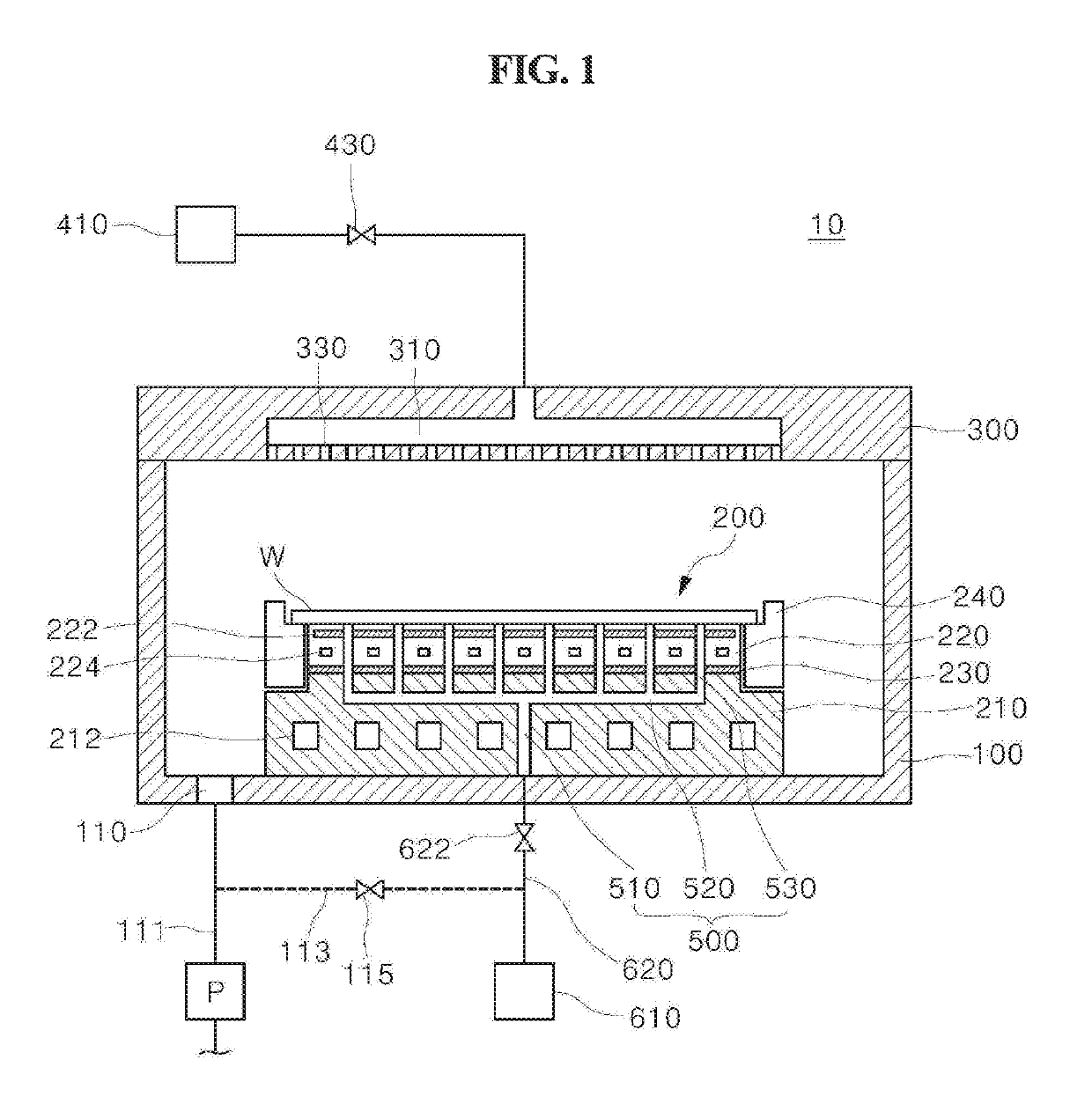
[0035]FIG. 1 is a cross-sectional view of a substrate processing apparatus according to an embodiment of the present invention.

[0036]With reference to FIG. 1, the substrate processing apparatus 10 includes a chamber 100, a substrate supporting member 200, and a gas injection unit 300.

[0037]The chamber 100 provides an interior space where the substrate processing process is performed. The substrate processing process can be performed in a vacuum atmosphere, and an exhaust port 11...


PUM

PropertyMeasurementUnit
sizesaaaaaaaaaa
shapeaaaaaaaaaa
diameteraaaaaaaaaa

Abstract

The present invention relates to a substrate supporting member and a substrate processing method. A gas flow path supplying a heat transfer gas to a rear surface of a substrate is provided in the substrate supporting member according to an embodiment of the present invention. Furthermore, a gas flow restricting member restricting gas flow to a different extent from each other according to a direction of the gas flow is provided at the gas flow path or at an external heat transfer gas supply pipe connected to the gas flow path. According to the present invention, by providing the gas flow restricting member restricting the gas flow to a different extent from each other according to the direction of the gas flow, there are effects of minimizing the time required for exhausting the heat transfer gas while preventing the arcing from occurring in a heat transfer gas flow path.

Description

CROSS REFERENCE TO RELATED APPLICATION[0001]The present application claims priority to Korean Patent Application No. 10-2017-0134982, filed Oct. 18, 2017, the entire contents of which is incorporated herein for all purposes by this reference.BACKGROUND OF THE INVENTIONField of the Invention[0002]The present invention relates to a substrate supporting member provided with a heat transfer gas flow path and a substrate processing apparatus including the same.Description of the Related Art[0003]In processing a substrate for fabrication of a semiconductor device or display, it is necessary to maintain the substrate uniformly at a predetermined temperature. To this end, the substrate supporting member for supporting the substrate is provided with a temperature control means such as a heater, a refrigerant path, or the like. For smooth heat transfer between the temperature control means and the substrate, a heat transfer gas flow path for supplying heat transfer gas such as helium (He) and...

Claims


Application Information

Patent Timeline
Patent Type & Authority Applications(United States)
IPC IPC(8): H01J37/32
CPCH01J37/32724H01J37/32449H01J2237/002H01L21/67011H01L21/68714H01L21/67109H01L21/67248H01L21/6831H01L21/67103H01L21/6835H01J37/32082H01J37/32715C23C16/4586
Inventor LEE, SANG KEE
Owner SEMES CO LTD
Learn More