High voltage arm assembly with integrated resistor, automatic high voltage deflection electrode locator, and special insulation

a high-voltage arm and resistor technology, applied in the field of inkjet printing, can solve the problems of resistor failure, stiff cable which is difficult to route, and attack and compromise the functionality of resistor, and achieve the effect of reducing arcing, minimizing the exposure of resistor to corrosive elements, and simplifying installation

Inactive Publication Date: 2008-02-19
VIDEOJET TECH INC
View PDF5 Cites 2 Cited by
  • Summary
  • Abstract
  • Description
  • Claims
  • Application Information

AI Technical Summary

Benefits of technology

[0012]According to certain aspects of an embodiment of the present invention, a deflection electrode assembly is provided for use in a continuous ink jet printer of the type which projects a stream of ink drops toward a substrate and controls placement of the ink drops on the substrate by selectively charging the individual ink drops and passing the charged ink drops through an electric field created by the deflection electrode assembly. The deflection electrode assembly includes a high voltage electrode, a low voltage electrode, and an insulating housing for positioning the high and low voltage electrodes in a predetermined spaced relationship along the ink drop stream. The insulating housing has an opening for supporting the high voltage electrode at a predetermined distance from the low voltage electrode. Moreover, a portion of the insulating housing is partially between the high voltage electrode and the low voltage electrode. The portion of the insulating housing between the high voltage electrode and the low voltage electrode minimizes arcing by exposing the high voltage electrode along the path of the ink drop stream. The deflection electrode assembly further comprises a resistor which is hermetically sealed within the insulating housing. The resistor is connected in series between an external, high voltage power source and the high voltage electrode. Placing the resistor inside the insulating housing minimizes the resistor's exposure to corrosive elements and simplifies installation.

Problems solved by technology

As such, the environment of the resistor is typically filled with corrosive inks and cleaning solutions which may attack and compromise the functionality of the resistor.
The wrapping results in a stiff cable which is difficult to route and place among various tubes and lines during assembly and maintenance of the print head.
Further, over time, the corrosive liquids can penetrate the wrappings, causing the resistor to fail.
If the gap between the electrodes is not optimized, the strength of the deflection field may be compromised, resulting in poor print quality and / or generating printer faults due to drops being deflected in undesirable locations.
Manual configuration of the gap between the electrodes is prone to human error, thus exposing the printer to sub-optimal performance.
This phenomenon has been reported in U.S. Pat. No. 6,848,774 for “Ink Jet Printer Deflection Electrode Assembly having a Dielectric Insulator.” Typically, the insulation is a loose piece, which is vulnerable to coming off during cleaning, or other operations.
If the insulation does come off, the high voltage electrode may arc to the low voltage electrode, and the ink jet will operate improperly.
Furthermore, such a system and method may incorporate insulation so it is not easily detached.

Method used


Image

  • High voltage arm assembly with integrated resistor, automatic high voltage deflection electrode locator, and special insulation
  • High voltage arm assembly with integrated resistor, automatic high voltage deflection electrode locator, and special insulation
  • High voltage arm assembly with integrated resistor, automatic high voltage deflection electrode locator, and special insulation

Examples


Embodiment Construction

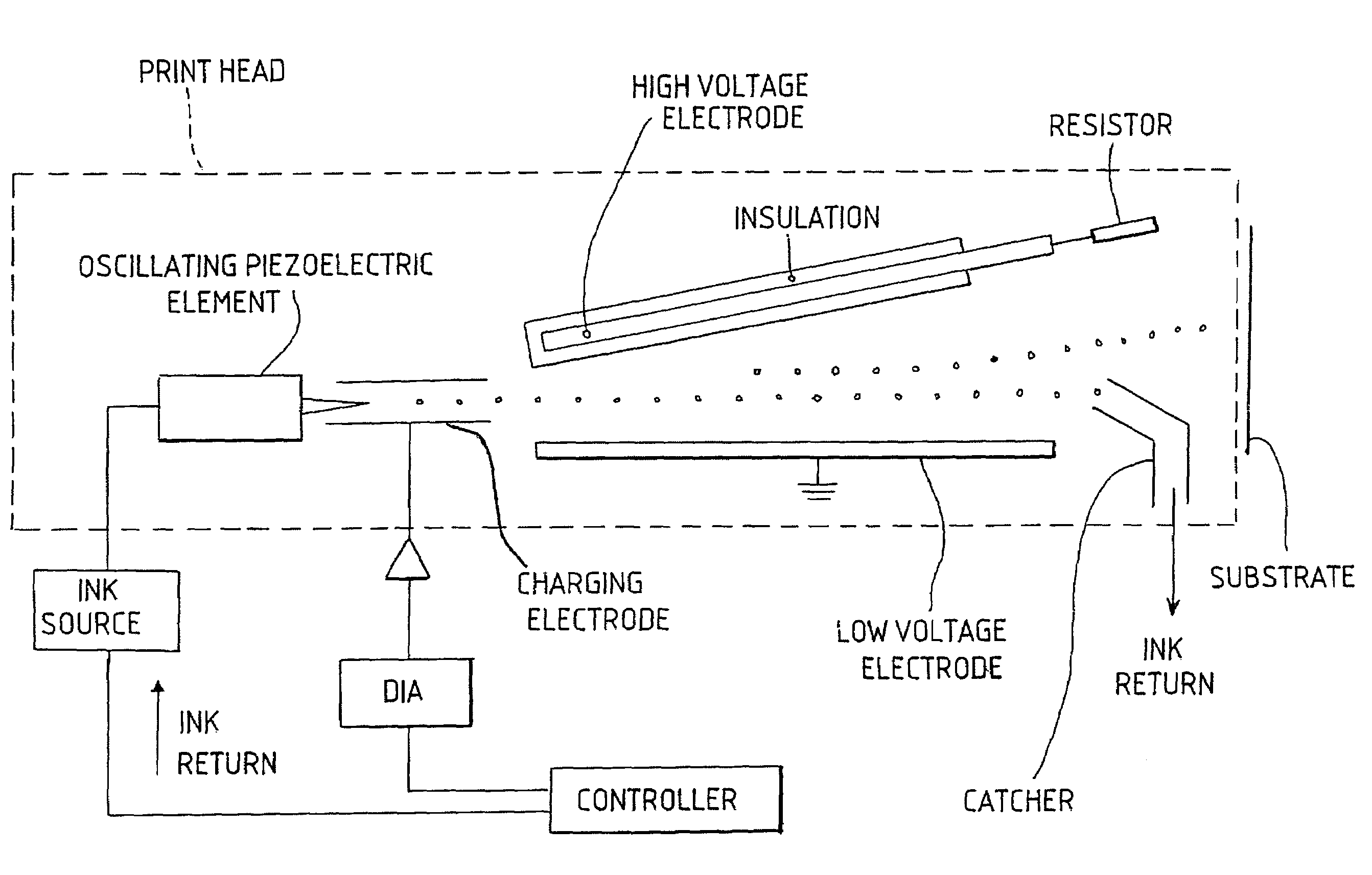
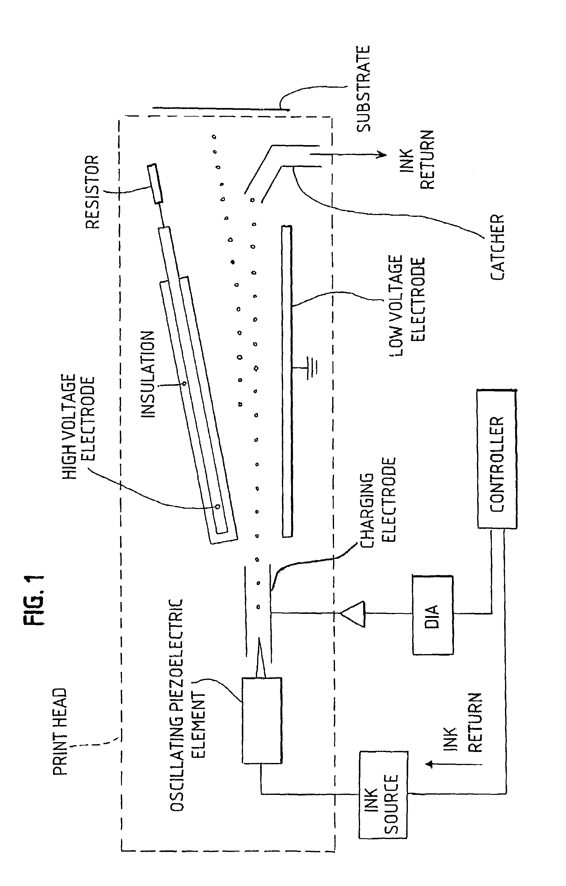
[0027]Referring to the drawings, a deflection electrode assembly 200 according to certain aspects of an embodiment of the present invention includes a high voltage deflection electrode 210, a low voltage (or ground) deflection electrode 220, and an insulating housing 230. As is explained in greater detail below, the insulating housing 230 functions to maintain the high and low voltage electrodes 210, 220 in a predetermined spacing relative to one another. The insulating housing 230 may be formed from any suitable dielectric material, but is preferably plastic. An external circuit (not shown) is connected to the deflection electrodes 210, 220 to create a deflection field between the electrodes so that the drops are vertically deflected in relation to their individual charges. For ease of reference herein, the deflection electrodes 210, 220 may be referred to as the high voltage deflection electrode 210 and the low voltage deflection electrode 220, or simply as the high voltage electr...


PUM


Abstract

According to an embodiment of the present invention, a deflection electrode assembly is provided for use in a continuous ink jet printer of the type which projects a stream of ink drops toward a substrate and controls placement of the ink drops on the substrate by selectively charging the individual ink drops and passing the charged ink drops through a deflection field created by the deflection electrode assembly. The deflection electrode assembly includes a high voltage electrode, a low voltage electrode, and an insulating housing which positions the high and low voltage electrodes in a predetermined spaced relationship along the ink drop stream. The insulating housing also has an internal resistor in electrical connection to the high voltage electrode and an external circuit. The insulating housing also contains an insulating member which supports the high voltage electrode as well as minimizes the possibility for arcing between the two electrodes.

Description

RELATED APPLICATIONS[0001]This application claims priority of provisional application Ser. No. 60 / 581,045 filed on Jun. 17 2004.FEDERALLY SPONSORED RESEARCH OR DEVELOPMENT[0002][Not Applicable]MICROFICHE / COPYRIGHT REFERENCE [0003][Not Applicable]BACKGROUND OF THE INVENTION[0004]The present invention relates to ink jet printing, and in particular to an improved deflection electrode assembly for a continuous ink jet printer.[0005]Continuous ink jet printers are well known in the field of industrial coding and marking, and are widely used for printing information, such as expiry dates, on various types of substrate passing the printer on production lines. As shown in FIG. 1, a jet of ink is broken up into a regular stream of uniform ink drops by an oscillating piezoelectric element. The drops then pass a charging electrode where the individual drops are charged to selected voltages. The drops then pass through a transverse electric field (deflection field) provided across a pair of def...

Claims


Application Information

Patent Timeline
Patent Type & Authority Patents(United States)
IPC IPC(8): B41J2/09B41J29/38H01L41/22H01L41/23
CPCB41J2/09B41J29/38
Inventor SHRIVASTAVA, DILIPRYBICKI, MICK
Owner VIDEOJET TECH INC
Why Eureka
Try Eureka