
Ionic fluid flow accelerator

a technology of accelerator and ionic fluid, applied in the direction of variable capacitor, corona discharge, instruments, etc., can solve the problem of generating more heat than their predecessor devices, and achieve the effect of maximizing efficiency, minimizing arcing, and maximizing alignmen

Inactive Publication Date: 2013-07-16
TESSERA INC
View PDF11 Cites 1 Cited by
  • Summary
  • Abstract
  • Description
  • Claims
  • Application Information

AI Technical Summary

Benefits of technology

This solution enables the creation of a virtually silent, low-cost, and efficient ionic air flow accelerator suitable for thermal management in electronic devices, effectively addressing the cooling needs of modern electronics by maximizing air flow rate and minimizing arcing, thus improving device performance and operation.

Problems solved by technology

Modern electronic devices contain more circuitry and components than earlier generations of these devices, causing them to generate more heat than their predecessor devices.

Method used


Image

  • Ionic fluid flow accelerator
  • Ionic fluid flow accelerator
  • Ionic fluid flow accelerator

Examples


first embodiment

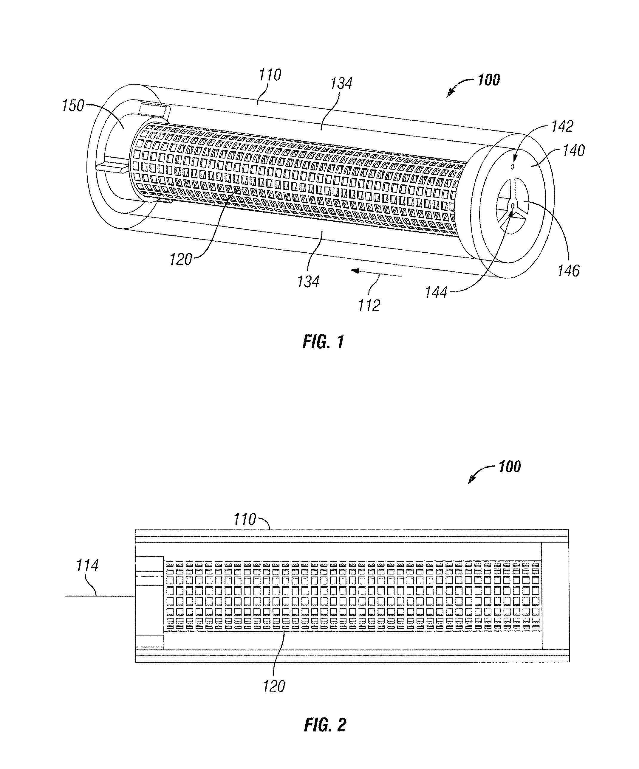
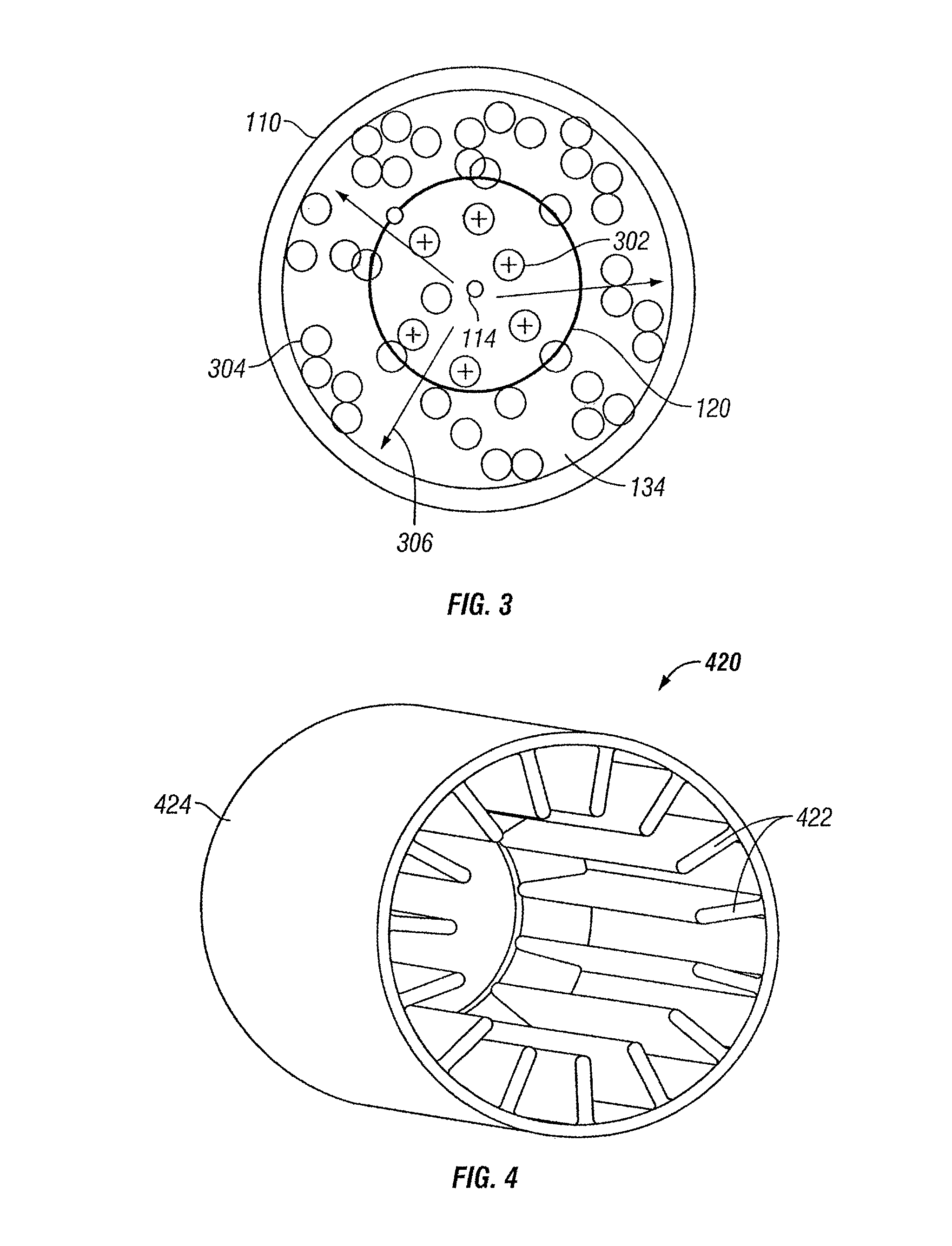
[0029]FIG. 1 illustrates a three-dimensional perspective view of an ionic air flow accelerator device 100 which occupies a cylindrically-shaped housing 110, hereafter referred to as outer tube 110. FIG. 2 is a side plan view of ionic air flow accelerator device 100. For purposes of showing other structures of ionic air flow accelerator device 100, outer tube 110 is shown as being made of transparent material in FIGS. 1 and 2, but it is understood that it need not be transparent. End-cap 140 is disposed at one end of outer tube 110, and comprises an aperture 144 through which passes a first electrical conductor 114 (shown in FIG. 2). Aperture 144 extends substantially through the entire length of the center portion of cylindrically-shaped housing 110. End-cap 140 also comprises an aperture 142 through which passes a second conductor which is not shown in FIGS. 1 and 2. End-cap 140 further comprises one or more apertures 146 that permit air to enter the interior of ionic air flow acce...

second embodiment

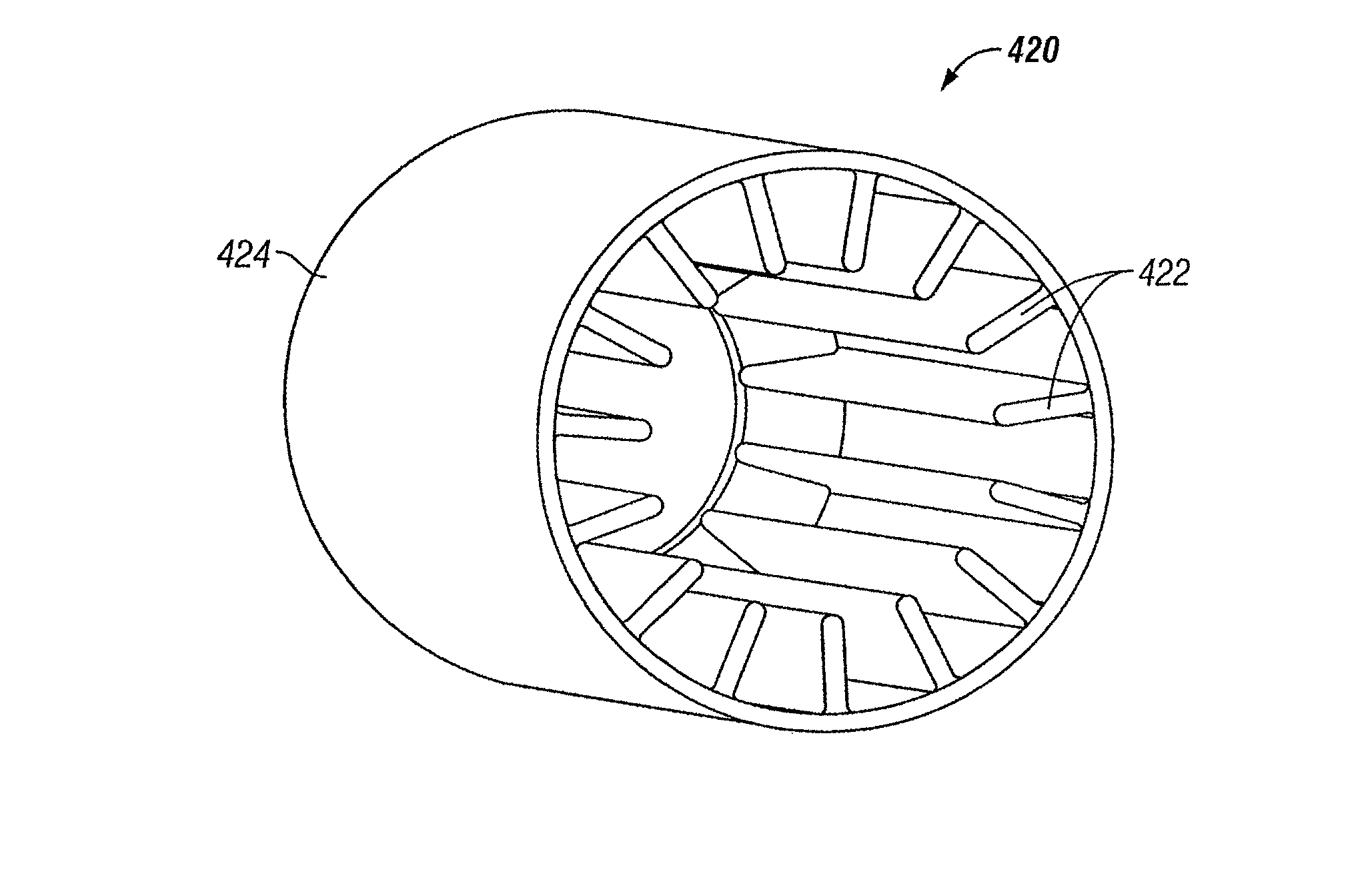
[0033]FIG. 4 is a three-dimensional perspective view of a collector structure for a cylindrically-shaped ionic air flow accelerator. Collector structure 420 comprises a series of conductive radial fins 422 disposed in and attached to a solid, grounded conductive tube 424 that surrounds the emitter (not shown in FIG. 4.) Collector structure 420 functions in a manner similarly to that of metal mesh collector structure 120 (FIG. 1). Grounded conductive tube 424 may provide increased safety. The configuration of radial fins 422 may contribute less resistance to the airflow.

third embodiment

[0034]FIG. 5 is a three-dimensional perspective view of a collector structure for a cylindrically-shaped ionic air flow accelerator. Collector structure 520 comprises a series of conductive radial fins 522 disposed in and attached to open grounded conductive tube 524 that surrounds the emitter (not shown in FIG. 5.) Collector structure 520 functions in a manner similarly to that of metal mesh collector structure 120 (FIG. 1). Open grounded conductive tube 524 allows the moving air to exhaust radially. This embodiment pulls ambient air into the cylindrically-shaped structure from one or both ends.


PUM


Abstract

An electrohydrodynamic fluid accelerator apparatus includes a corona electrode having an axial shape and configured to receive a first voltage. The electrohydrodynamic fluid accelerator apparatus includes a collector electrode disposed coaxially around the at least one corona electrode and configured to receive a second voltage. Application of the first and second voltages on the corona electrode and the collector electrode, respectively, causes fluid proximate to the corona electrode to ionize and travel in a first direction between the corona electrode and the collector electrode, thereby causing other fluid molecules to travel in a second direction to generate a fluid stream. In at least one embodiment of the invention, the ionized fluid proximate to the emitter electrode travels in a radial direction from the corona electrode to the collector electrode, causing the other fluid molecules to travel in an axial direction to thereby generate the fluid stream.

Description

CROSS-REFERENCE TO RELATED APPLICATION(S)[0001]This application claims benefit under 35 U.S.C. §119(e) of provisional application No. 61 / 046,792, filed Apr. 21, 2008, entitled “Collector Structure for Ionic Air Flow Accelerator,” naming Matt Schwiebert and Kenneth Honer as inventors, which application is incorporated herein by reference in its entirety.BACKGROUND[0002]1. Field of the Invention[0003]The subject matter of the present application is related to a type of electrohydrodynamic (also known as electro-fluid-dynamic) technology that uses corona discharge principles to generate ions and electrical fields to control the movement of fluids such as air, or other types of fluids, and more particularly to embodiments of collector structures in an ionic air flow accelerator device.[0004]2. Description of the Related Art[0005]Principles of the ionic movement of fluids include ion generation using a first electrode (often termed the “corona electrode” or the “corona discharge electrod...

Claims


Application Information

Patent Timeline
Patent Type & Authority Patents(United States)
IPC IPC(8): H05F3/06
CPCB03C3/41B03C3/49B03C2201/10B03C2201/14B03C2201/04
Inventor SCHWIEBERT, MATTHEWHONER, KENNETHJEWELL-LARSEN, NELS
Owner TESSERA INC
Learn More