Fixture and implant

a technology of fixing and implant, which is applied in the direction of impression caps, dental surgery, and fastening prostheses, can solve the problems of insufficient connection between the fixture and the abutment, cracks in the central hole of the fixture, and broken fixtures, so as to prevent cracks in the central hole, ceramic fixtures and implants can be highly strengthened, and the effect of preventing cracks

Active Publication Date: 2019-04-25
NANTOH
View PDF7 Cites 0 Cited by
  • Summary
  • Abstract
  • Description
  • Claims
  • Application Information

AI Technical Summary

Benefits of technology

[0038]According to the present invention, a fixture on which defects are rarely caused in the central hole can be achieved. On the ceramic fixture, defects in the central hole can be prevented. Thus, it can be ensured to miniaturize the fixture and the implant.
[0039]Also, according to the present invention, it

Problems solved by technology

However, if the implant is miniaturized, there is a problem that defects such as cracks are likely to occur in the central hole of the fixture.
Thereby, the connection between the fixture and the abutment is insufficient, or the fixture is broken.
In particular, since a ceramic is a brittle materi

Method used


Image

  • Fixture and implant
  • Fixture and implant
  • Fixture and implant

Examples


Embodiment Construction

[0047]Embodiments of the present invention will be explained with reference to the drawings. Various sizes and the like shown in the following description are merely examples.

Dental Implant 1

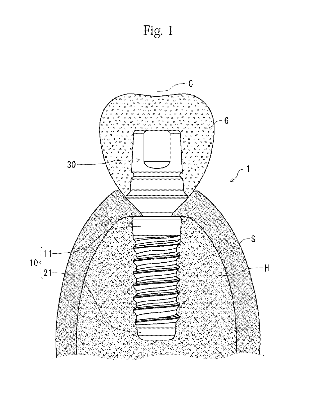
[0048]FIG. 1 illustrates a dental implant 1 according to an embodiment of the present invention.

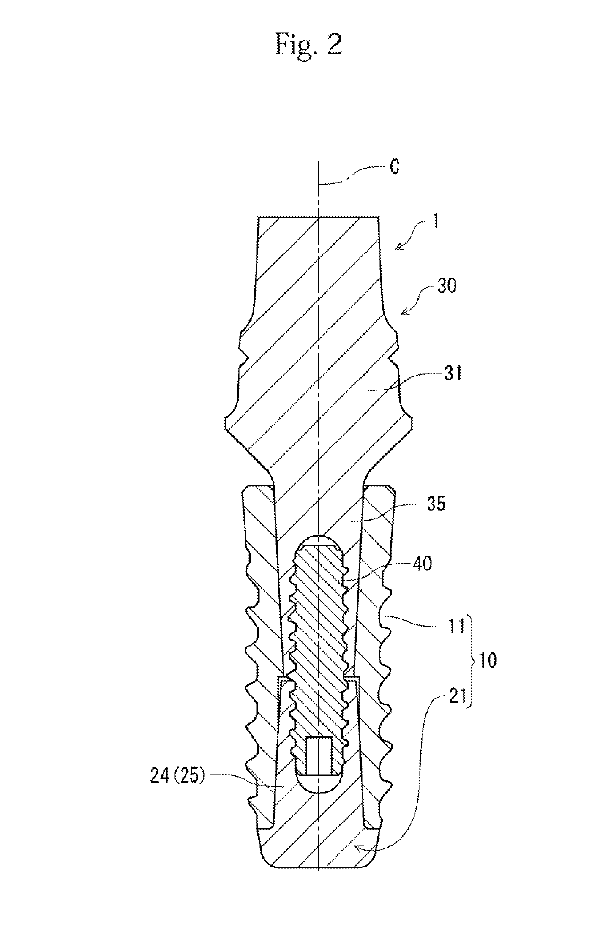
[0049]FIG. 2 illustrates a longitudinal sectional view of the dental implant 1.

[0050]The dental implant (implant) 1 comprises a fixture 10 fixed to an alveolar bone (bone) H, and an abutment 30 fitted into the fixture 10. An implant crown 6 is mounted on the abutment 30.

[0051]A root end side below the implant crown 6 is covered with a gum S.

[0052]The longitudinal direction (direction along a central axis C) of the dental implant 1 is referred to as a Z direction or a vertical.

[0053]In the Z direction, the side of the implant crown 6 is referred to as a −Z direction or a top end side. The end in the −Z direction is referred to as a top end (first end). In the Z direction, the side of the fixture 10 is ...


PUM

PropertyMeasurementUnit
Fractionaaaaaaaaaa
Fractionaaaaaaaaaa
Fractionaaaaaaaaaa

Abstract

A fixture (10) to be embedded in a bone (H), comprising: a fixture body (11) through which a central hole (13) penetrates over the entire length thereof; and a cap body (21) which closes an opening on a root end side of the central hole (13). The cap body (21) has a first shaft section (24) to be fitted into the central hole (13). The central hole (13) has a first tapered hole section (14) which decreases in diameter from the root end side toward a top end side, and the cap body (21) has a first tapered shaft section (25) to be fitted into the first tapered hole section (14).

Description

TECHNICAL FIELD[0001]The present invention relates to a fixture and an implant, e.g., a dental implant which is embedded in a jaw bone.[0002]The present application claims priority on the basis of Japanese Patent Application Laid-Open No. 2016-079232, Japanese Patent Application Laid-Open No. 2016-079233, and Japanese Patent Application Laid-Open No. 2016-079234 filed on Apr. 12, 2016 in Japan, and the contents of the application are incorporated herein.BACKGROUND ART[0003]Implants to be embedded in bodies have been attracting attention. For example, when a tooth root of a permanent tooth is lost due to caries or breakage, a dental implant is inserted in a hole provided in an alveolar bone and fixed thereto.[0004]This dental implant is composed of a fixture (artificial tooth root) to be fixed to an alveolar bone, and an abutment (supporting stage) connected to the fixture. An implant crown (artificial crown) is mounted on the abutment.[0005]A dental implant (fixture, abutment) is fo...

Claims


Application Information

Patent Timeline
IPC IPC(8): A61C8/00A61K6/02A61K6/087A61K6/891
CPCA61C8/0012A61C8/0018A61C8/008A61C8/0016A61K6/0205A61K6/087A61C8/00A61C13/225A61K6/802A61K6/891A61C8/0022A61C8/0039A61C8/0057A61C8/0068A61C8/0069A61C13/0006
Inventor ISHIWATA, TERUO
Owner NANTOH
Why Eureka
Try Eureka