

Imaging lens assembly
a technology of imaging lens and assembly, applied in the field of imaging technology, can solve the problems of increasing the size the difficulty of the available imaging lens assembly, and achieve the effects of high magnification and resolution, and shortening the total length of the imaging lens assembly
- Summary
- Abstract
- Description
- Claims
- Application Information
AI Technical Summary
Benefits of technology
Problems solved by technology
Method used
Image

Examples
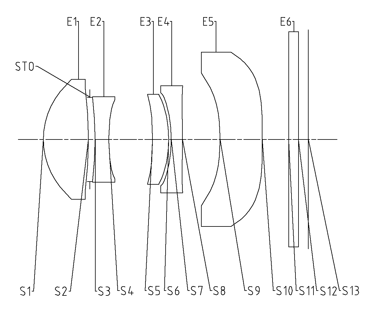
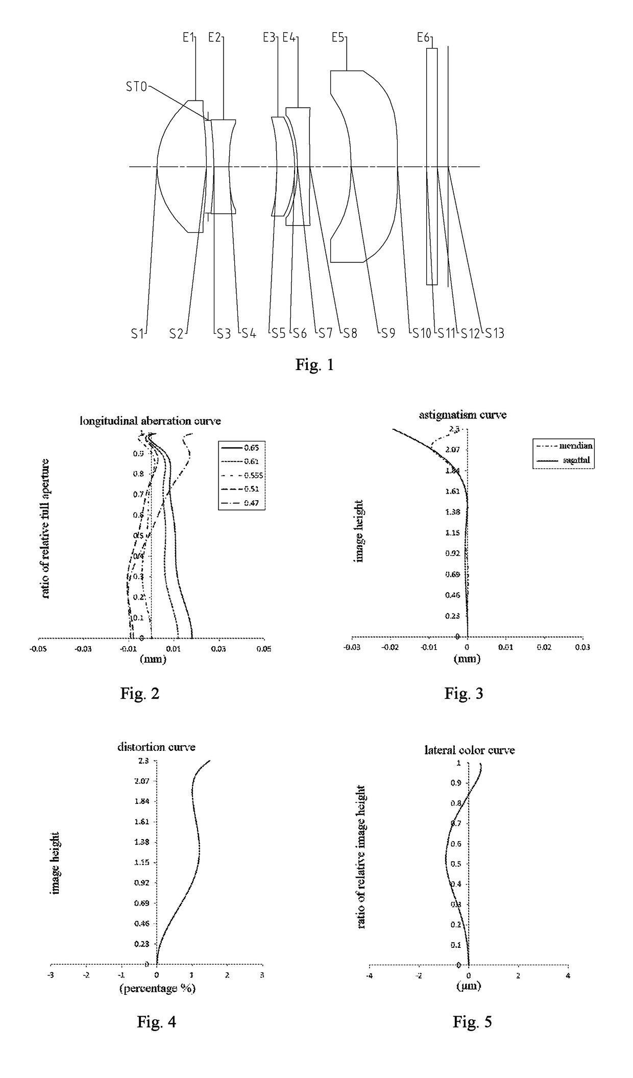
example 1
[0110]In example 1, the imaging lens assembly meets the conditions in the following tables:
[0111]
TABLE 1MaterialSurface No.Surface typeCurvature radiusThickness(refractive index / abbe)Conic coefficientOBJsphericalinfinityinfinityS1aspheric1.57780.96561.54, 56.1−0.3593S2aspheric−9.42010.030023.8031STOsphericalinfinity0.1153S3aspheric−6.32530.28911.64, 23.539.3661S4aspheric3.78480.9406−33.3684S5aspheric−7.25240.34461.64, 23.5−84.9134S6aspheric−2.60590.0559−2.0829S7aspheric−2.62890.24001.54, 56.1−28.2494S8aspheric−16.33470.807299.9989S9aspheric−4.18450.90341.54, 56.1−20.9603S10aspheric−33.95500.564446.2104S11sphericalinfinity0.21001.52, 64.2S12sphericalinfinity0.1364S13sphericalinfinity
[0112]
TABLE 2Surface No.A4A6A8A10A12A14A16S1 1.1133E−02−9.1921E−041.0459E−02−1.0122E−023.3048E−03 1.2412E−03−1.1810E−03 S2−2.8913E−02 7.1463E−02−7.3838E−02 5.2215E−02−3.2302E−02 1.4269E−02−2.9144E−03 S3−4.7660E−02 2.0641E−01−1.7614E−01 4.5183E−021.2096E−01−1.3973E−016.7465E−02S4 6.6894E−02 6.2359E−021....
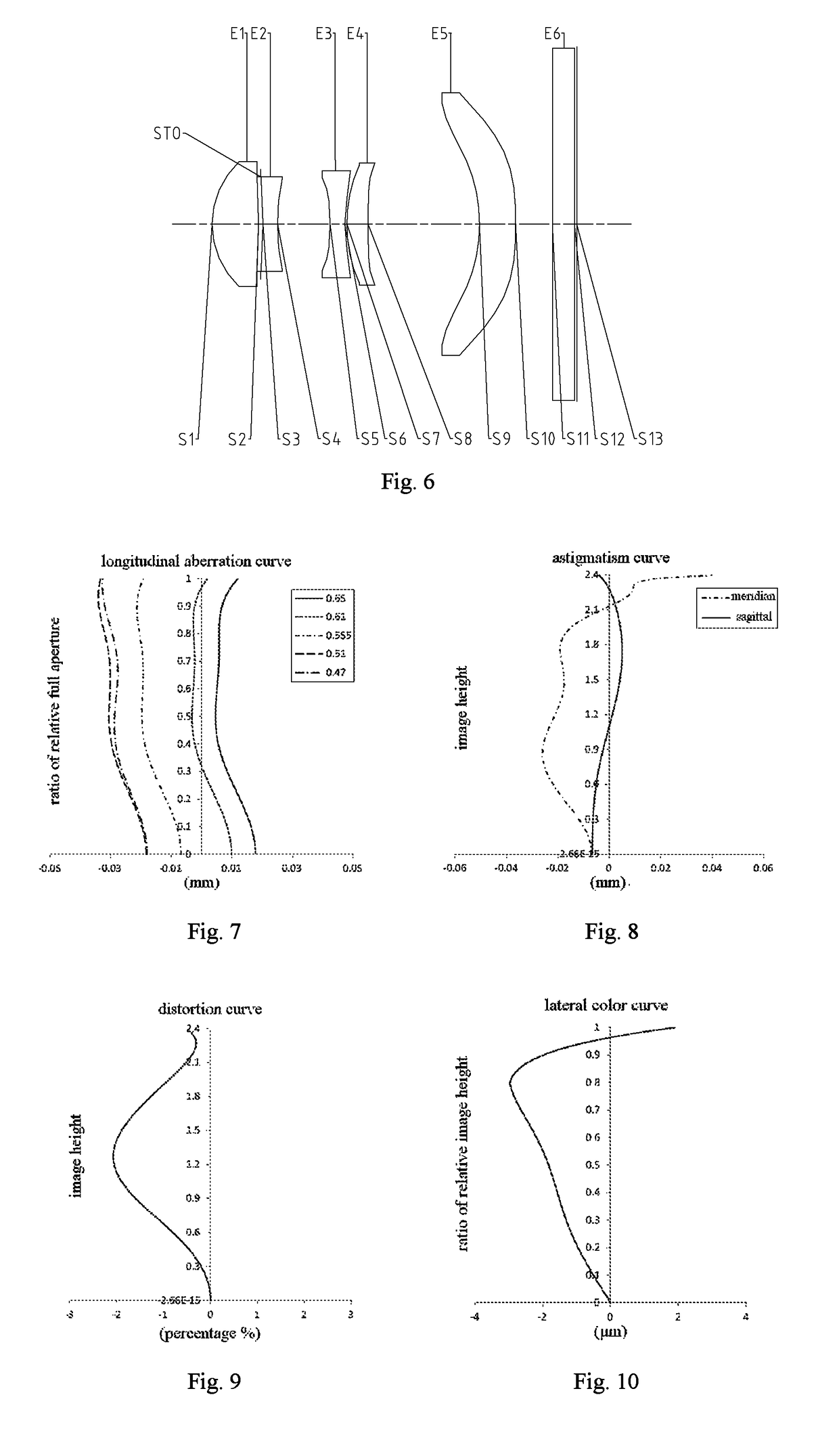
example 2
[0114]In example 2, the imaging lens assembly meets the conditions in the following tables:
[0115]
TABLE 3MaterialSurface No.Surface typeCurvature radiusThickness(refractive index / abbe)Conic coefficientOBJsphericalinfinityinfinityS1aspheric1.13900.63201.54, 56.1−0.3068S2aspheric−6.34580.0300−48.3835STOsphericalinfinity0.0300S3aspheric−3.74760.20001.64, 23.3−31.9157S4aspheric4.91420.7129−58.3971S5aspheric−4.18470.20001.74, 44.90.0000S6aspheric1.73390.0300−10.7526S7aspheric2.05710.28751.64, 23.30.0000S8aspheric−110.42991.5150−0.0002S9aspheric−2.43010.49221.54, 56.1−0.3803S10aspheric−7.45580.5000−6.2818S11sphericalinfinity0.30001.52, 64.2S12sphericalinfinity0.0300S13sphericalinfinity
[0116]
TABLE 4Surface No.A4A6A8A10A12A14A16S12.1841E−027.9372E−039.9168E−033.8145E−03000S23.3956E−023.8717E−02−2.1216E−02 1.5821E−03000S31.2408E−01−2.2426E−02 8.4235E−042.0995E−02000S42.5303E−01−1.1178E−01 3.6187E−021.0276E−01000S5−4.3743E−01 3.5561E−01−3.9903E−01 −6.5392E−01 000S6−1.7297E−01 1.1238E−01...
example 3
[0118]In example 3, the imaging lens assembly meets the conditions in the following tables:
[0119]
TABLE 5MaterialSurface No.Surface typeCurvature radiusThickness(refractive index / abbe)Conic coefficientOBJsphericalinfinityinfinityS1aspheric1.58730.83611.54, 56.1−0.3338S2aspheric−14.78280.0300−100.0000STOsphericalinfinity0.1118S3aspheric−7.66400.25341.64, 23.548.3971S4aspheric3.99371.0644−48.6876S5aspheric7.60190.30601.64, 23.5−41.7534S6aspheric−7.44970.075832.5708S7aspheric−2.71020.24001.54, 56.1−30.3428S8aspheric62.75320.9730−99.9409S9aspheric−5.91500.88941.54, 56.1−8.7731S10aspheric−189.77070.484446.2104S11sphericalinfinity0.21001.52, 64.2S12sphericalinfinity0.2076S13sphericalinfinity
[0120]
TABLE 6Surface No.A4A6A8A10A12A14A16S1 1.1225E−02 1.6558E−039.4999E−03−9.4671E−033.9635E−03 1.1822E−03−1.2047E−03 S2−2.0278E−02 6.8305E−02−7.6622E−02 5.2327E−02−3.0432E−02 1.5231E−02−3.9067E−03 S3−5.5093E−02 2.0505E−01−1.9175E−01 3.6162E−021.3195E−01−1.2802E−014.2721E−02S4 4.4541E−02 2.3135E−02...
PUM
 Abstract
Description
Claims
Application Information