Optical module including photoelectric conversion element and optical coupling member

a technology of optical coupling member and photoelectric conversion element, which is applied in the field of optical modules, can solve the problems of lowering the rigidity of the optical fiber, and achieve the effects of increasing the length of the optical fiber holding the optical, reducing the dimension in the thickness direction of the optical module, and increasing the length of the optical modul

Active Publication Date: 2015-10-06
HITACHI METALS LTD
View PDF11 Cites 1 Cited by
  • Summary
  • Abstract
  • Description
  • Claims
  • Application Information

AI Technical Summary

Benefits of technology

[0009]Also, a way to shorten the entire length of the above described optical module (the length in the extension direction of the optical fiber) is considered to be, e.g., to miniaturize the second substrate and the third substrate and shorten the insertion guide groove. However, shortening the insertion guide groove leads to the optical fiber holding rigidity lowering, and the optical fiber tending to slip out from the insertion guide groove. This is a structural constraint on shortening the entire length of the optical module.
[0010]Accordingly, it is an object of the present invention to provide an optical module capable of ensuring miniaturization thereof while securely holding an optical fiber.
[0027]The optical module according to the invention allows ensuring miniaturization thereof while securely holding the optical fiber.

Problems solved by technology

However, shortening the insertion guide groove leads to the optical fiber holding rigidity lowering, and the optical fiber tending to slip out from the insertion guide groove.

Method used


Image

  • Optical module including photoelectric conversion element and optical coupling member
  • Optical module including photoelectric conversion element and optical coupling member
  • Optical module including photoelectric conversion element and optical coupling member

Examples


embodiments

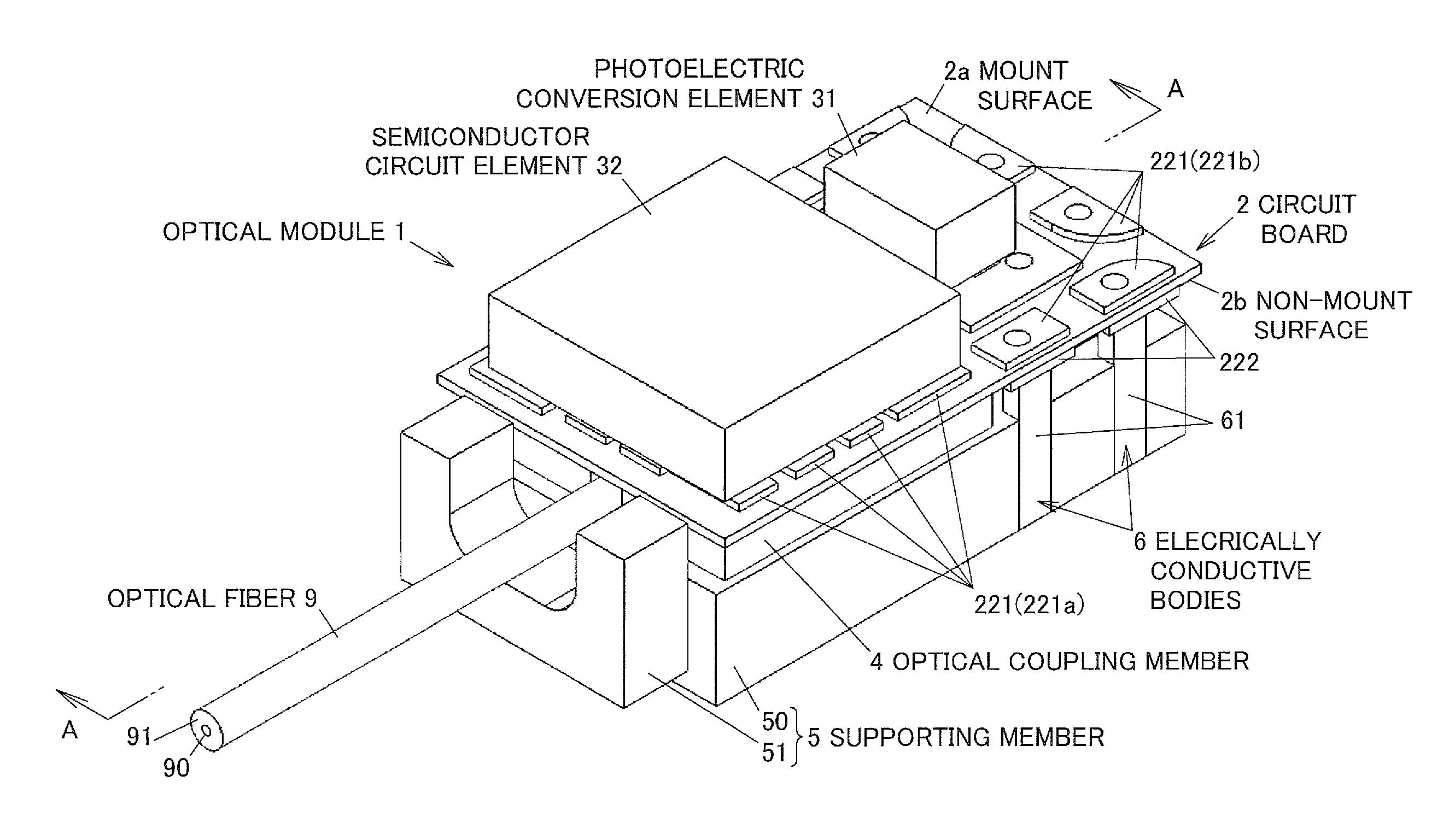
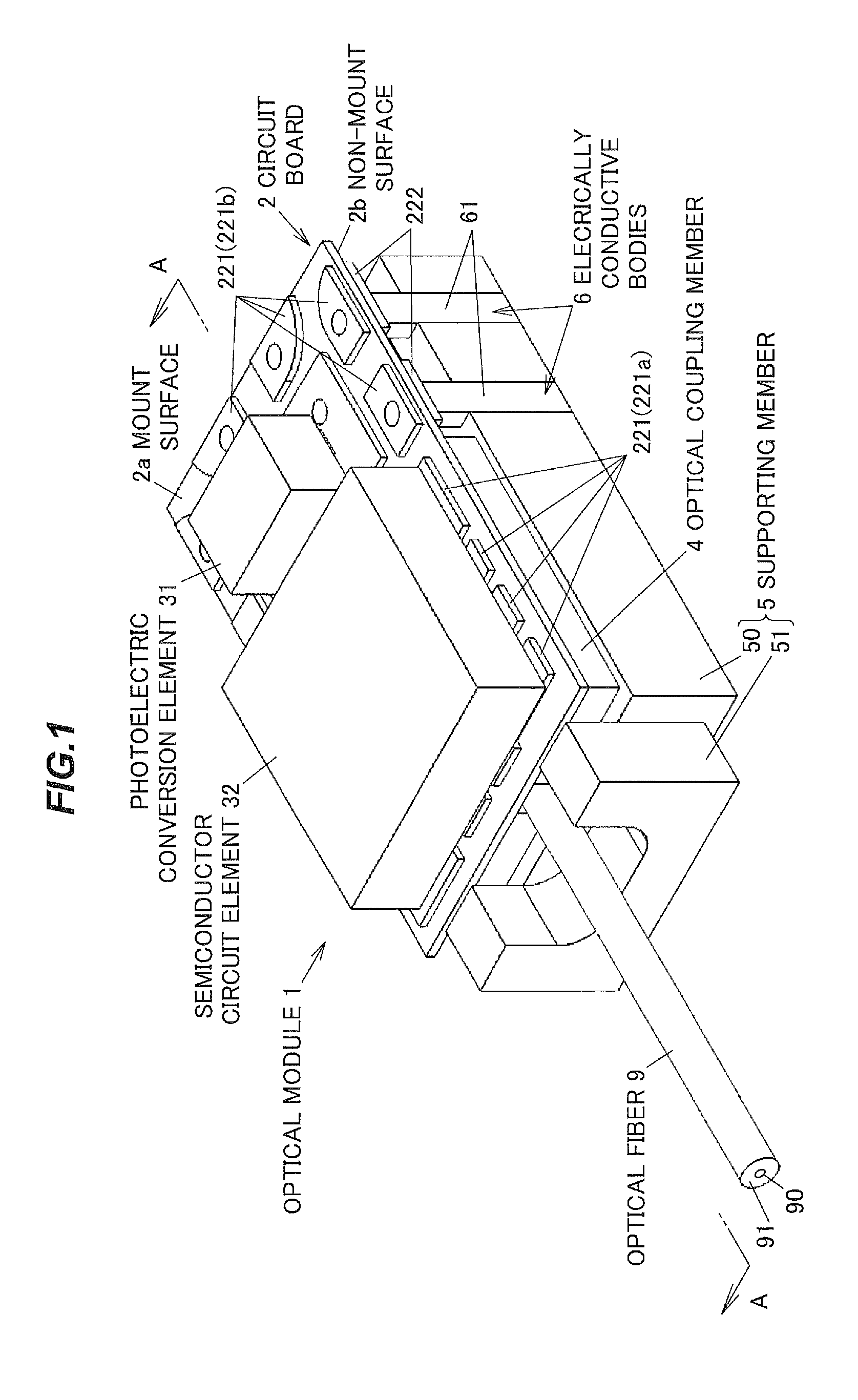
[0046]Below is described one configuration example of an optical module in a first embodiment according to the invention, by reference to FIGS. 1 to 11.

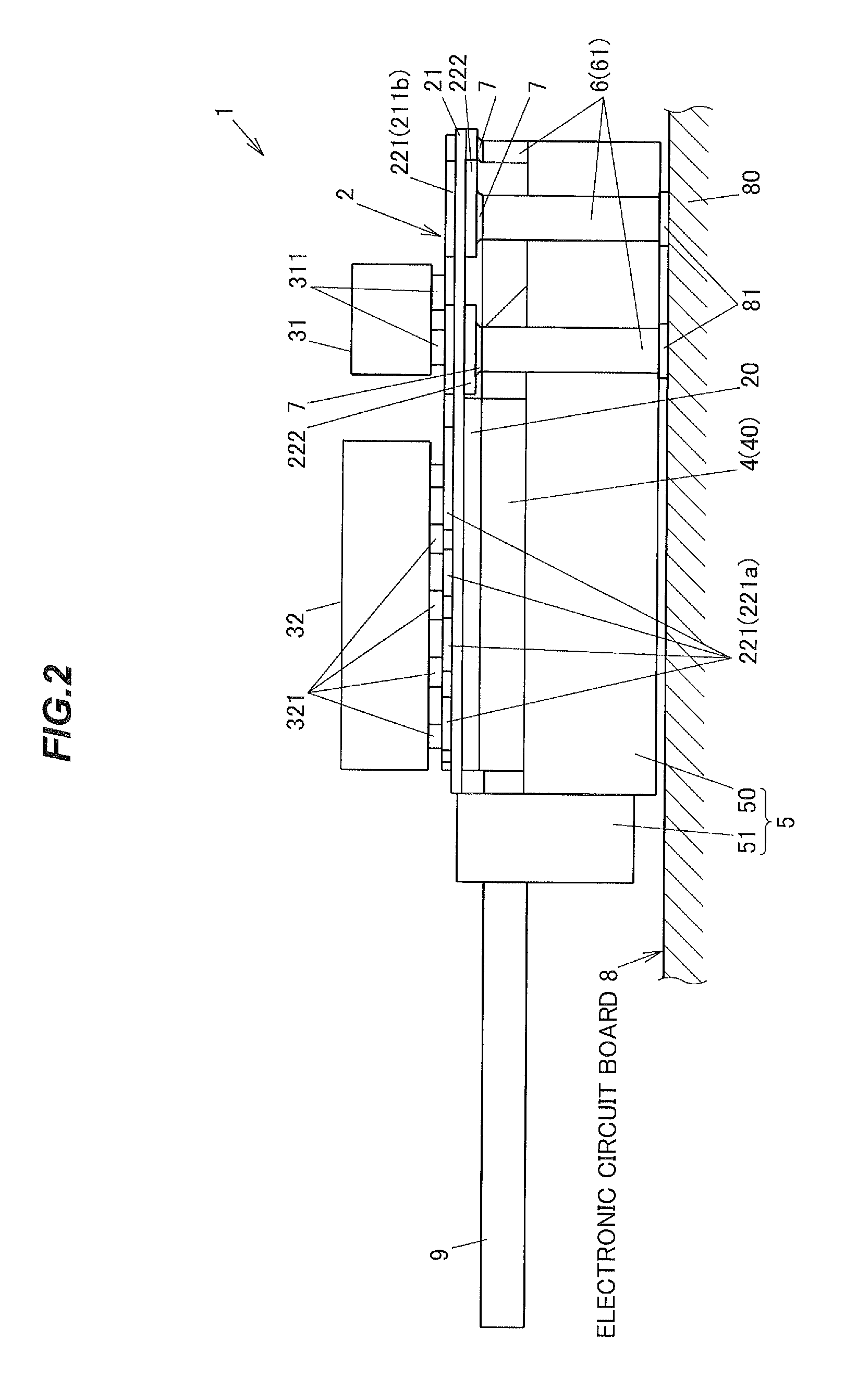
[0047]FIG. 1 is a perspective view showing an optical module 1 in the present embodiment. FIG. 2 is a side view showing the optical module 1 mounted on an electronic circuit board 8. FIG. 3 is a cross sectional view taken along line A-A of FIG. 1 showing the optical module 1 cut along an axis line of an optical fiber 9 mounted to the optical module 1.

[0048]As shown in FIG. 2, this optical module 1 is used to be mounted on an electronic circuit board 8. The electronic circuit board 8 is a glass epoxy substrate with a plurality of copper foils 81 stuck to a plate shaped base material 80 resulting from a glass fiber being soaked with an epoxy resin and thermally cured. The electronic circuit board 8 is mounted with electronic components not shown, such as a CPU (Central Processing Unit), a memory element and the like. The optical fiber ...

second embodiment

[0101]Next is described a second embodiment of the present invention with reference to FIGS. 12 to 14. In these figures, elements having functions substantially common to those described in the first embodiment are given the same or corresponding reference numerals, and duplicated descriptions thereof are omitted.

[0102]FIG. 12 is a perspective view showing an optical module 1A in this embodiment. FIG. 13 is a perspective view showing the optical module 1A viewed at a different angle from in FIG. 12. FIGS. 14A and 14B are perspective views, respectively, showing a supporting member 5A of the optical module 1A.

[0103]Whereas in the first embodiment it has been described that the pair of side walls 511 of the pooling portion 51 are shaped into the rectangular prism, a pair of walls 511A in the optical module 1A in the second embodiment are shaped into a column. The pair of walls 511A together with a bottom wall 510A constitutes a pooling portion 51A.

[0104]Further, whereas in the first e...


PUM


Abstract

An optical module includes a circuit board including a mount surface and a non-mount surface opposite the mount surface, a photoelectric conversion element mounted on the mount surface of the circuit board, an optical coupling member for holding an optical fiber and optically coupling the optical fiber and the photoelectric conversion element, a semiconductor circuit element mounted on the mount surface of the circuit board, and electrically connected to the photoelectric conversion element, a plate-shaped supporting member arranged so as to sandwich the optical coupling member between the supporting member and the circuit board, and an electrically conductive body supported by the supporting member, extended in a thickness direction of the supporting member, and connected at one end to an electrode provided on the non-mount surface of the circuit board.

Description

[0001]The present application is based on Japanese patent application No. 2012-015824 filed on Jan. 27, 2012, the entire contents of which are incorporated herein by reference.BACKGROUND OF THE INVENTION[0002]1. Field of the Invention[0003]The present invention relates to an optical module, which transmits a signal through an optical fiber.[0004]2. Description of the Related Art[0005]Conventionally, an optical module for transmitting or receiving a signal through an optical fiber which is equipped with a photoelectric (optical to electric or electric to optical) conversion element for converting electrical energy into optical energy, or optical energy into electrical energy has been known as disclosed by e.g. Japanese Patent Laid-Open No. 2011-95295 (JP-A-2011-95295).[0006]The optical module disclosed by JP-A-2011-95295 includes plate-shaped first to fourth substrates, an IC substrate, and a connector for electrically connecting the optical module to another circuit device. The firs...

Claims


Application Information

Patent Timeline
Patent Type & Authority Patents(United States)
IPC IPC(8): G01J1/02G02B6/42
CPCG01J1/0204G01J1/0209G02B6/423G02B6/428G02B6/4214G02B6/4244G02B6/4245G02B6/4265
Inventor YU, JUHYUNYASUDA, HIROKIHIRANO, KOUKISUNAGA, YOSHINORI
Owner HITACHI METALS LTD
Why Eureka
Try Eureka