System and method for controlling time dilation in time-sensitive networks

a time-sensitive network and time-dilation technology, applied in the field of computerized communication networks, can solve the problems of frame arrival or delay of time-sensitive network frames, clocks in the networks have not achieved the level of accuracy and stability to perfectly schedule time-sensitive network flows,

Active Publication Date: 2019-04-25
GENERAL ELECTRIC CO
View PDF7 Cites 12 Cited by
  • Summary
  • Abstract
  • Description
  • Claims
  • Application Information

AI Technical Summary

Benefits of technology

[0005]In one embodiment, a method includes determining a clock drift and a clock variance of each node in plural nodes of a time-sensitive Ethernet network, determining an accumulated clock offset along a time-sensitive network path in the time-sensitive network based on the clock drifts and the clock variances that are determined, determining a guard band having a dynamic size based on the accumulated clock offset, and restricting when Ethernet frames are communicated through the nodes by communicating the guard band with the dynamic size to one or more of the nodes.
[0006]In one embodiment, a system includes one or more processors configured to determine a clock drift and a clock variance of each node in plural nodes of a time-sensitive network. The one or more processors also are configured to determine an accumulated clock offset along a time-sensitive network path in the time-sensitive network based on the clock drifts and the clock variances that are determined. The one or more processors also are configured to determine a guard band having a dynamic size based on the accumulated clock offset and to communicate the guard band with the dynamic size to the nodes. The one or more processors are configured to allocate the guard band to at least one of the nodes. The guard band restricts when Ethernet frames are communicated through the at least one of the nodes.

Problems solved by technology

But, clocks in the networks have not achieved the level of accuracy and stability to perfectly schedule time-sensitive network flows.
Clock synchronization errors may lead the frames to arrive ahead or behind their schedule.
In this case, time-sensitive network frames can be delayed in an unpredictable manner, thus defeating the purpose of a deterministic Ethernet.

Method used


Image

  • System and method for controlling time dilation in time-sensitive networks
  • System and method for controlling time dilation in time-sensitive networks
  • System and method for controlling time dilation in time-sensitive networks

Examples


Embodiment Construction

[0015]One or more embodiments of the inventive subject matter described herein provide systems and methods that use efficient determinism of time-sensitive networking to increase cybersecurity by examining positive feedback between non-classical physics and time-sensitive networking. The difference of elapsed time that occurs due to relativity is treated by the timing and synchronization standard as a contribution to clock drift of network nodes (e.g., switches) and a time-aware scheduler device of a time-sensitive network is configured relative to a time reference of a grandmaster clock device of the network, but then loses simultaneity with a local relative time reference of the scheduler device.

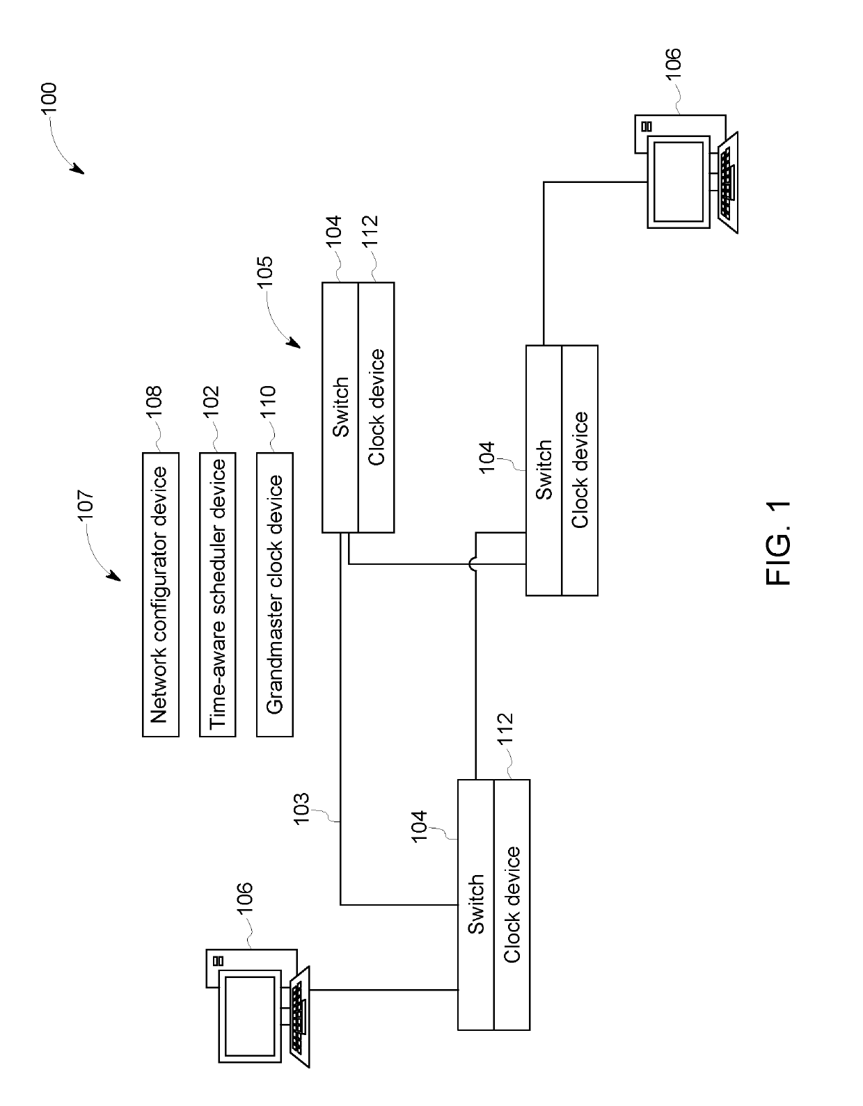
[0016]FIG. 1 schematically illustrates one embodiment of a network control system 107 of a time-sensitive network system 100. The components shown in FIG. 1 represent hardware circuitry that includes and / or is connected with one or more processors (e.g., one or more microprocessors, field ...


PUM


Abstract

A system and method determine a clock drift and a clock variance of each node in plural nodes of a time-sensitive Ethernet network. An accumulated clock offset along a time-sensitive network path in the time-sensitive network is determined based on the clock drifts and the clock variances. A guard band having a dynamic size is determined based on the accumulated clock offset. The times at which Ethernet frames are communicated through the nodes are restricted by communicating the guard band with the dynamic size to one or more of the nodes.

Description

CROSS-REFERENCE TO RELATED APPLICATIONS[0001]This application claims priority to U.S. Provisional Patent Application No. 62 / 575,719, which was filed on 23 Oct. 2017, and the entire disclosure of which is incorporated herein by reference.FIELD[0002]The subject matter described herein relates to computerized communication networks, such as time-sensitive networks.BACKGROUND[0003]The IEEE 802.1 Time-Sensitive Networking Task Group has created a series of standards that describe how to implement deterministic, scheduled Ethernet frame delivery within an Ethernet network. Time-sensitive networking benefits from advances in time precision and stability to create efficient, deterministic traffic flows in an Ethernet network.[0004]But, clocks in the networks have not achieved the level of accuracy and stability to perfectly schedule time-sensitive network flows. Clock synchronization errors may lead the frames to arrive ahead or behind their schedule. In this case, time-sensitive network fr...

Claims


Application Information

Patent Timeline
Patent Type & Authority Applications(United States)
IPC IPC(8): H04J3/06H04L9/32H04L29/06
CPCH04J3/0697H04L9/3297H04L63/0227H04L63/12H04L63/108H04J3/0667H04K1/00H04L9/0852H04L63/061H04L63/123
Inventor BUSH, STEPHEN FRANCISMANTELET, GUILLAUME
Owner GENERAL ELECTRIC CO
Why Eureka
Try Eureka