Method for taking seismic measurements

a technology for seismic measurements and equipment, applied in the field of equipment and methods for recording downhole seismic measurements, can solve the problems of inaccurate timing accuracy of any recording taken downhole, tool strings may be disconnected from the surface, etc., and achieve the effects of improving coupling, reducing downhole and or system noise, and increasing acquisition efficiency

Inactive Publication Date: 2008-09-11
SCHLUMBERGER TECH CORP
View PDF63 Cites 27 Cited by
  • Summary
  • Abstract
  • Description
  • Claims
  • Application Information

AI Technical Summary

Benefits of technology

[0005]A stabilizer may be attached to the tool string and may have at least two stabilizer blades with a pocket adapted to receive at least three geophones oriented at three different orthogonal axes. In some embodiments there are three to five stabilizer blades and there is a set of geophones in each. Typically at least one of the stabilizer blades may contact the formation thereby improving the coupling that the set of geophones may have with the formation. Since there are several sets of geophones more recordings may be taken per each seismic shot produced at the surface; thus increasing the acquisition efficiency. The recordings from the several sets of the geophones may also be averaged or otherwise treated mathematically to reduce downhole and or system noise, allowing for more accurate data per surface seismic shot The acquisition sequence may be completely controlled by the engineer at surface and complex down hole state determining algorithms are not required. The downhole sensors and electronics may be adapted to take measurements according to programmable acquisition parameters which may be controlled at the surface. Such parameters may include gain, sample rate, filtering, and combinations thereof.

Problems solved by technology

However, there are instances where the tool string may be disconnected from the surface such as adding or removing pipe during drilling or tripping and other instances which breaks communication between the top hole and downhole clocks.
During these breaks timing accuracy of any recordings taken downhole may be inaccurate since the downhole clocks may drift.

Method used


Image

  • Method for taking seismic measurements
  • Method for taking seismic measurements
  • Method for taking seismic measurements

Examples


Embodiment Construction

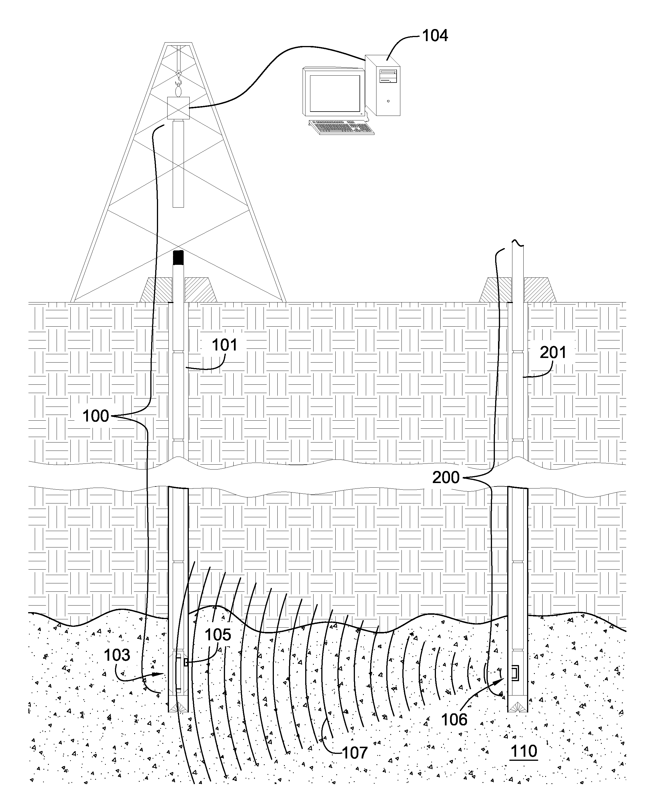
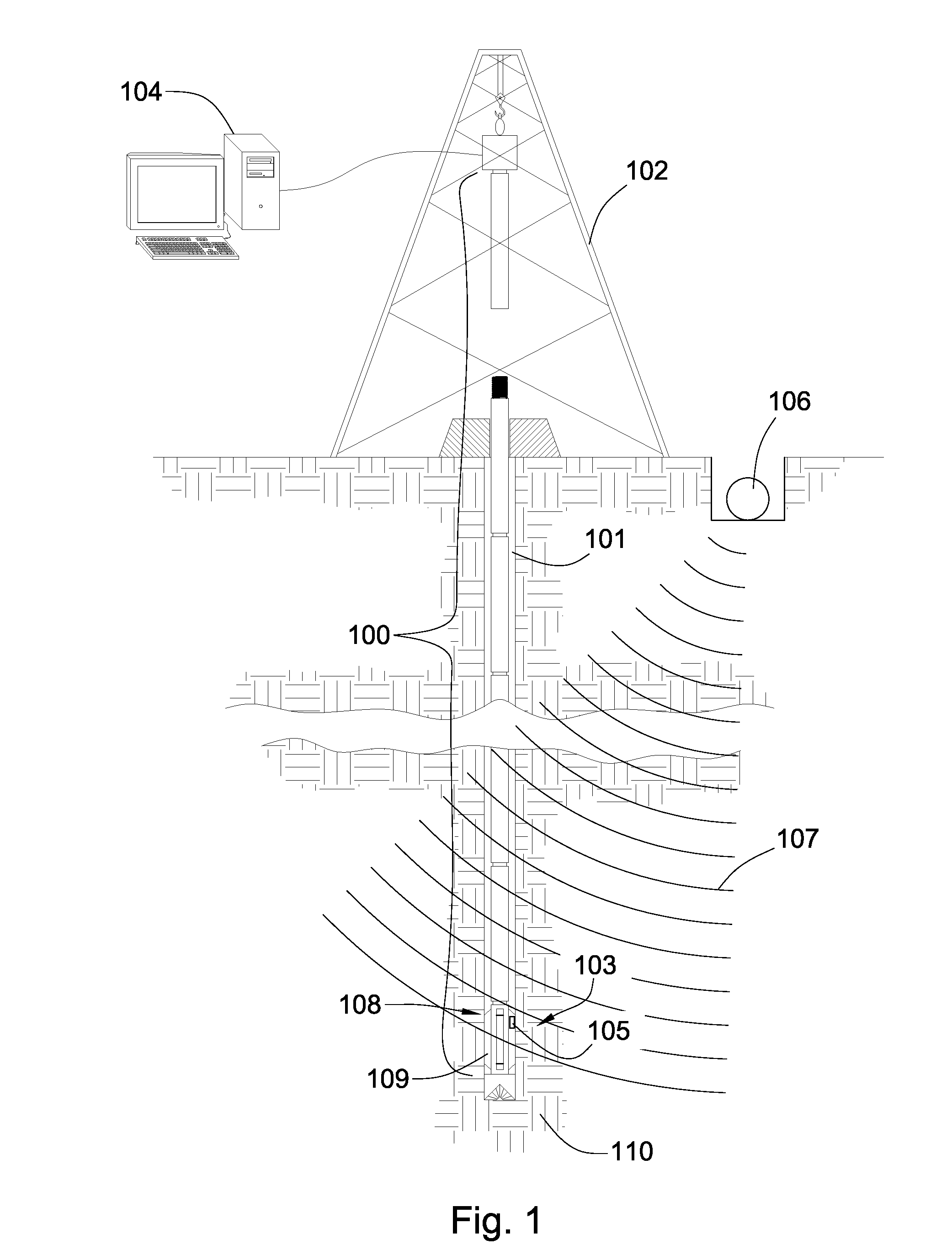
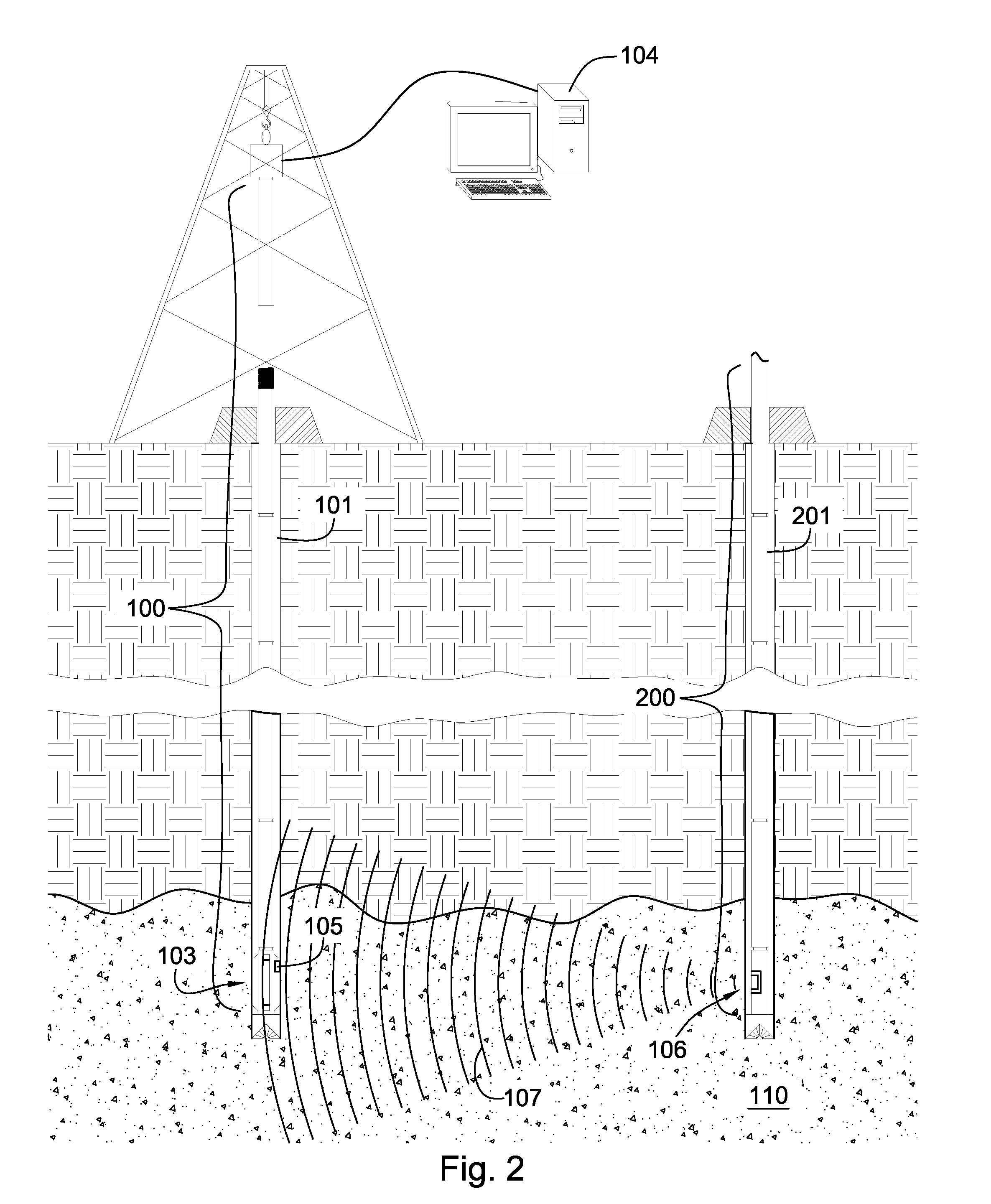
[0016]FIG. 1 shows a perspective diagram of a downhole tool string 100 suspended in a well bore 101. A derrick 102 supports the tool string 100. In this embodiment the tool string 100 may be a drill string. In other embodiments, the tool string 100 may also be a production string, an injection string, a casing string, a horizontal drill string or combinations thereof. A downhole network 103 may be integrated into the tool string 100. The network 103 may transmit data to surface equipment. A downhole network compatible with the present invention is disclosed in U.S. Pat. No. 6,670,880 to Hall which is herein incorporated by reference for all that it discloses. In the preferred embodiment, the network 103 transmits data to top-hole equipment for real time analysis. The top-hole equipment comprises a clock source 104. The top-hole equipment may be a GPS, network servers, surface equipment, computers, laptops, satellites, recording equipment, processing software or combinations thereof....


PUM


Abstract

In one aspect of the present invention a method has steps for taking downhole measurements. A network integrated into a downhole tool string in a well bore may be in communication with a downhole sensor, the downhole sensor having a downhole clock that may be in communication over the network with and synchronized with a top-hole clock source. A signal source may be within a transmitting distance of the downhole sensor and may be activated. The downhole sensor records signals from the signal source at a recorded time when the network is disconnected from the top-hole clock source. When the network is reconnected, the downhole clock and the top-hole clock source are re-synchronized. The clock drift that occurred during the disconnection may be calculated. The recorded time may be adjusted to reflect what it would have been if the downhole clock had been synchronized with the top-hole clock source.

Description

BACKGROUND OF INVENTION[0001]This invention relates to oil and gas drilling, and more particularly to apparatus and methods for recording downhole seismic measurements. The introduction of the wired pipe networks into the oil and gas drilling industry allows downhole clocks to be continuously synchronized with top hole clock sources. U.S. Pat. No. 7,142,129 and U.S. Patent Publications 2005 / 0284645 and 2006 / 0221768, which are herein incorporated by reference for all that they disclose, deal with various aspects of taking downhole seismic measurements using wire pipe. However, there are instances where the tool string may be disconnected from the surface such as adding or removing pipe during drilling or tripping and other instances which breaks communication between the top hole and downhole clocks. During these breaks timing accuracy of any recordings taken downhole may be inaccurate since the downhole clocks may drift.BRIEF SUMMARY OF THE INVENTION[0002]In one aspect of the presen...

Claims


Application Information

Patent Timeline
Patent Type & Authority Applications(United States)
IPC IPC(8): E21B47/00
CPCG01V2200/12G01V1/42
Inventor HALL, DAVID R.DURRAND, CHRISTOPHER
Owner SCHLUMBERGER TECH CORP
Why Eureka
Try Eureka