Cutting blade holder

a cutting blade and holder technology, applied in the field of cutting blade holders, can solve the problems of troublesome replacement, time-consuming, string-shaped cutting blades being abraded or broken, etc., and achieve the effects of convenient adjustment of the holding position of the cutting blade, large shearing force, and effective prevention of cutting blade damag

Inactive Publication Date: 2019-05-02
HONDA MOTOR CO LTD
View PDF4 Cites 1 Cited by
  • Summary
  • Abstract
  • Description
  • Claims
  • Application Information

AI Technical Summary

Benefits of technology

[0006]Therefore, it is a primary object of the present invention to provide a cutting blade holder capable of adjusting the effective length of a string-shaped cutting blade without replacement of the same.
[0021]In the aforementioned cutting blade holder, it is preferable that the main body portion be provided with a protection plate larger in diameter than the main body portion and that the guide portion be disposed inside an outer peripheral edge portion of the protection plate in the radial direction. In this case, the protection plate being larger in diameter than the main body portion is provided, and thus, even when the protection plate is brought into contact with an obstacle while cutting grass and the like, a space corresponding to a difference between outer diameters of the main body portion and the protection plate is formed between the main body portion and the obstacle. Accordingly, it is possible to restrain the cutting blade from being interposed between the main body portion and the obstacle. Further, since the outer peripheral edge portion of the protection plate is disposed outside the guide portion in the radial direction, it is possible to restrain the cutting blade from being interposed between the guide portion and the obstacle while cutting grass and the like. Accordingly, in a simple configuration that the protection plate is provided on one end side in the axial direction of the main body portion, it is possible to suppress the damage, breaking or the like of the cutting blade further effectively.

Problems solved by technology

Occasionally, the string-shaped cutting blade is abraded or broken in the course of cutting works of grass and the like.
The replacement is troublesome and time-consuming.

Method used


Image

  • Cutting blade holder
  • Cutting blade holder
  • Cutting blade holder

Examples


Embodiment Construction

[0031]Hereinafter, a cutting blade holder according to the present invention will be described based on a preferred embodiment with reference to the accompanying drawings. Incidentally, in the following drawings, components which are the same or similar in function and effect will be designated by the same reference numerals and will be omitted from being repetitively described.

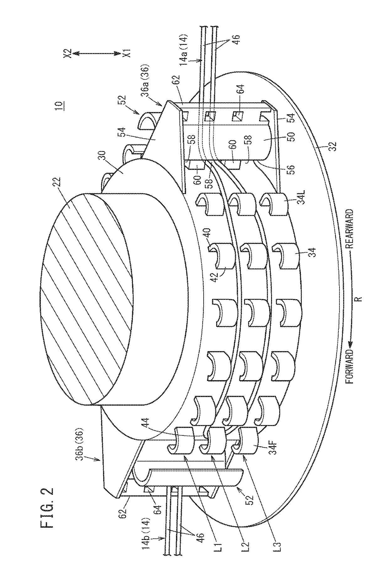
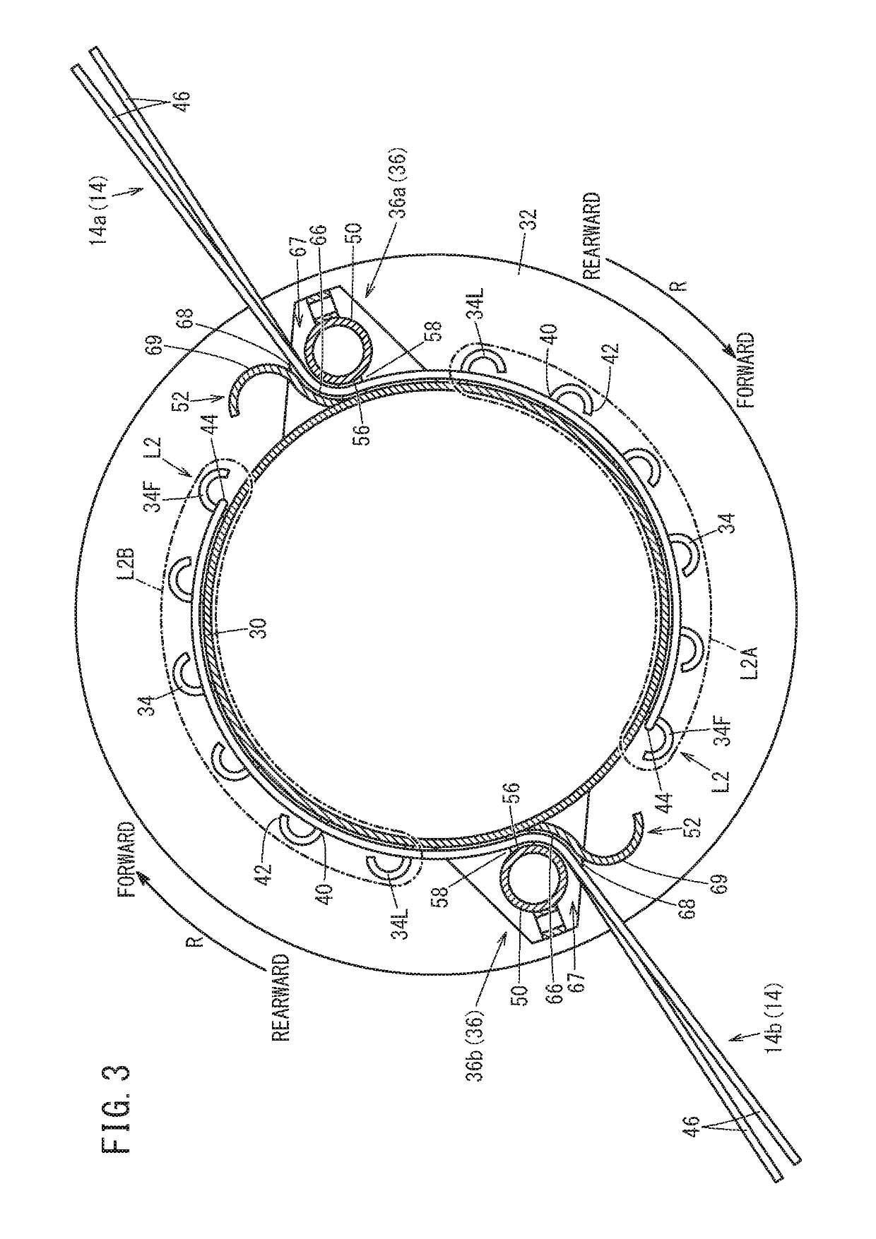
[0032]As shown in FIG. 1, in the present embodiment, description will be given regarding an example in which a cutting blade holder 10 is equipped in a string trimmer 12 of a shoulder type. However, without being limited to the string trimmer 12 of the shoulder type, the cutting blade holder 10 is applicable, similarly to the string trimmer 12, to various working machines which are capable of cutting objects (not shown) to be cut such as grass and the like by rotating a string-shaped cutting blade 14.

[0033]The string trimmer 12 is mainly equipped with a pipe-like operating rod 16, a drive shaft 18 extending t...


PUM


Abstract

A cutting blade holder holding a string-shaped cutting blade is provided with a main body portion rotationally driven by a driving source, a hook row having a plurality of hook portions which are each capable of anchoring the cutting blade and which are provided on an outer peripheral surface of the main body portion at intervals in a rotation direction of the main body portion, and a guide portion provided rearward of the hook row in the rotation direction and directing the cutting blade outward in a radial direction of the main body portion.

Description

CROSS-REFERENCE TO RELATED APPLICATION[0001]This application is based upon and claims the benefit of priority from Japanese Patent Application No. 2017-211527 filed on Nov. 1, 2017, the contents of which are incorporated herein by reference.BACKGROUND OF THE INVENTIONField of the Invention[0002]The present invention relates to a cutting blade holder holding a string-shaped cutting blade.Description of the Related Art[0003]String trimmers for cutting grass and the like with string-shaped cutting blades such as nylon cords or the like are provided with cutting blade holders holding the cutting blades. For example, U.S. Pat. No. 6,363,616 discloses a cutting blade holder configured by stacking a plurality of disc-like resin plates. Each of the resin plates is formed on one end side in the thickness direction with a circumferential groove of a fixed length and on the other end side in the thickness direction with a pair of projections facing each other with a distance therebetween in th...

Claims


Application Information

Patent Timeline
Patent Type & Authority Applications(United States)
IPC IPC(8): A01D34/416A01D34/90A01D34/84
CPCA01D34/4166A01D34/90A01D34/84A01D2101/00A01D34/4161
Inventor YAMAZAKI, NOBUO
Owner HONDA MOTOR CO LTD
Why Eureka
Try Eureka