Encoding and decoding hdr videos

Active Publication Date: 2019-05-02
KONINKLJIJKE PHILIPS NV
View PDF0 Cites 27 Cited by
  • Summary
  • Abstract
  • Description
  • Claims
  • Application Information

AI Technical Summary

Benefits of technology

[0034]Embodiments with more possibilities, although more complex, allow even

Problems solved by technology

The grader can see on a reference display what he is doing (e.g. on SDR ref display, and checking with the mast

Method used


Image

  • Encoding and decoding hdr videos
  • Encoding and decoding hdr videos
  • Encoding and decoding hdr videos

Examples


Embodiment Construction

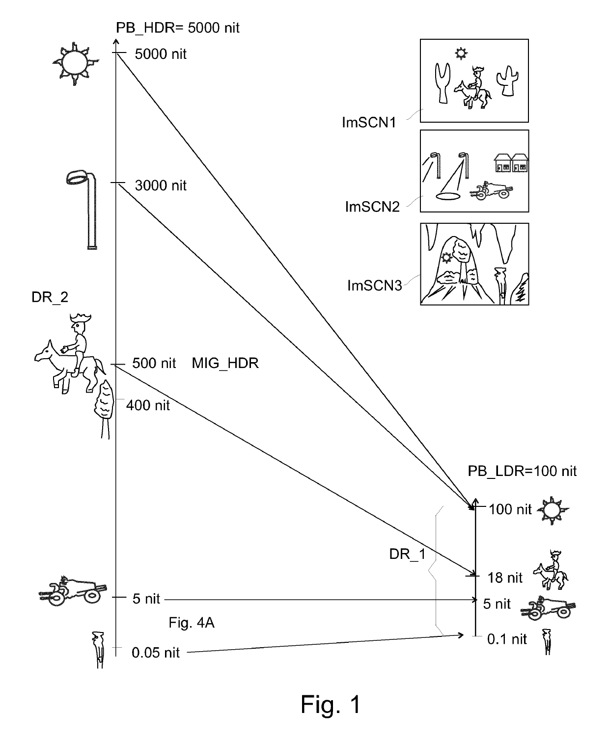
[0069]FIG. 5 shows an example of how one can typically model the transformation between the SDR image and the HDR image with curves, luminance (or luma) mapping curves. I.e. also when receiving a SDR image, being able to reconstruct the creation-side master HDR image approximately by applying the inverse curve. There may in some embodiments be various color transformations involved to calculate a region of pixels (e.g. corresponding to an object) in the secondary re-graded image (i.e. in our elucidation a HDR image, of PB_C=1000 nit, just as an example to be clear) on the basis of the geometrically corresponding pixels in the primary image, the SDR PB_C=100 nit image. E.g. local color transformations may be applied only to some regions and not to the rest of the image. However, for practical reasons, in many scenarios one wants simple transformations (usually on global, i.e. dependent on the pixel luma, and not its geometrical location in the image or other such non-color related pr...


PUM


Abstract

To enable a high quality HDR video communication, which can work by sending corresponding LDR images potentially via established LDR video communication technologies, which works well in practical situations, applicant has invented a HDR video decoder (600, 1100) arranged to calculate a HDR image (Im_RHDR) based on applying to a received 100 nit standard dynamic range image (Im_RLDR) a set of luminance 5 transformation functions, the functions comprising at least a coarse luminance mapping (FC), which is applied by a dynamic range optimizer (603), and a mapping of the darkest value (0) of an intermediate luma (Y′HPS), being output of the dynamic range optimizer, to a received black offset value (Bk_off) by a range stretcher (604), the video decoder comprising a gain limiter (611, 1105) arranged to apply an alternate luminance transformation function to 10 calculate a subset (502) of the darkest luminances of the HDR image, from corresponding darkest lumas (Y′_in) of the standard dynamic range image.

Description

FIELD OF THE INVENTION[0001]The invention relates to methods and apparatuses for encoding respectively decoding a temporally successive set of high dynamic range images, called herein a HDR video.BACKGROUND OF THE INVENTION[0002]Until a couple of years ago, all video was encoded according to the so-called low dynamic range (LDR) philosophy, also called standard dynamic range (SDR). That meant, whatever the captured scene was, that the maximum of the code (typically 8 bit luma Y′=255; or 100% voltage for analog display driving) should by standardized definition correspond to, i.e. be rendered on, a display with a peak brightness PB (i.e. the brightest white color it can render) being by standard agreement 100 nit. If people bought an actual display which was a little darker or brighter, it was assumed that the viewer's visual system would adapt so that the image would still look appropriate and even the same as on the reference 100 nit display, rather than e.g. annoyingly too bright ...

Claims


Application Information

Patent Timeline
IPC IPC(8): G06T5/00H04N19/186H04N19/60
CPCG06T5/007H04N19/186H04N19/60G06T2207/10024G06T2207/10016H04N19/30H04N19/85
Inventor TICHELAAR, JOHANNES YZEBRANDVAN MOURIK, JOHANNES GERARDUS RIJKSTESSEN, JEROEN HUBERT CHRISTOFFEL JACOBUSGORIS, ROELAND FOCCO EVERHARDMERTENS, MARK JOZEF WILLEMVANDEWALLE, PATRICK LUC ELSNIJLAND, RUTGER
Owner KONINKLJIJKE PHILIPS NV
Why Eureka
Try Eureka