
Display device and method for bonding array substrate and IC chip

Active Publication Date: 2019-05-02
WUHAN CHINA STAR OPTOELECTRONICS SEMICON DISPLAY TECH CO LTD
View PDF0 Cites 1 Cited by
  • Summary
  • Abstract
  • Description
  • Claims
  • Application Information

AI Technical Summary

Benefits of technology

The patent aims to provide a display device with improved quality by reducing positional shifts and short-circuit in the bump caused by conductive particles. The conductive particles are shaped to reduce fluidity and distributed to form electrical connections between metal terminals on the array substrate and the IC chip through a conductive adhesive. This solution helps to avoid the issue of short-circuit and guarantees the quality of the display panel.

Problems solved by technology

During the thermal pressing process, because the temperature raises to increase fluidity of the resin layer, the conducting particles, touching the bump, are forced into a gap due to bonding pressure, density of the conducting particles, which are at the gap, is greater than at the bump resulting in a short-circuit.
In summary, during the process of bonding the IC chip of the display panel in the prior art, the conductive particles distributed in a set location of the resin are affected by the fluidity of the resin, resulting in positional shifts, causing short-circuiting in the bump, thereby affecting quality of the display panel.

Method used


Image

  • Display device and method for bonding array substrate and IC chip
  • Display device and method for bonding array substrate and IC chip
  • Display device and method for bonding array substrate and IC chip

Examples


Embodiment Construction

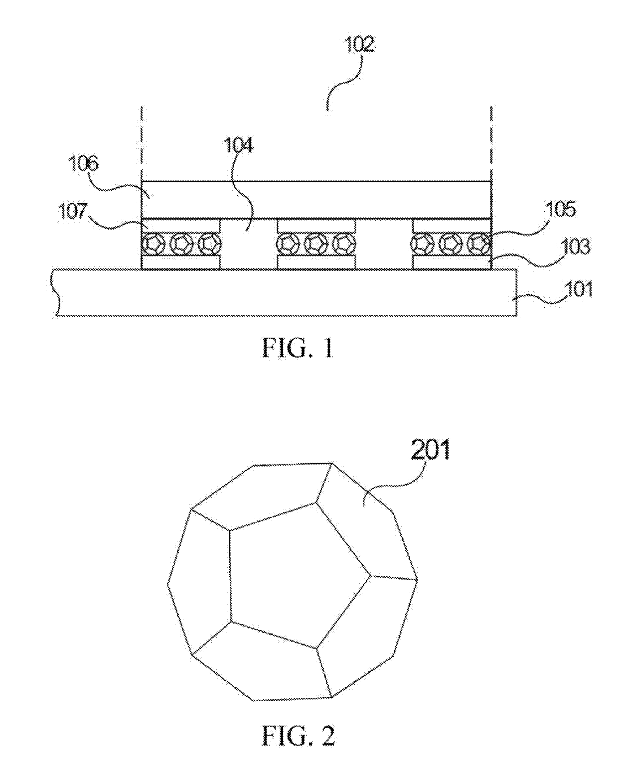
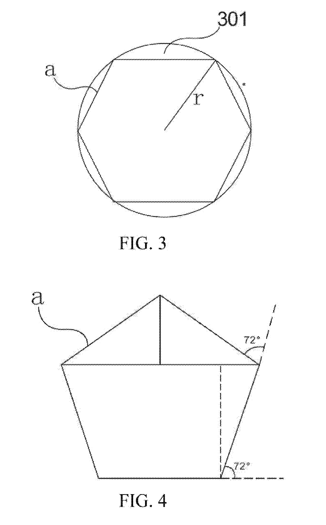
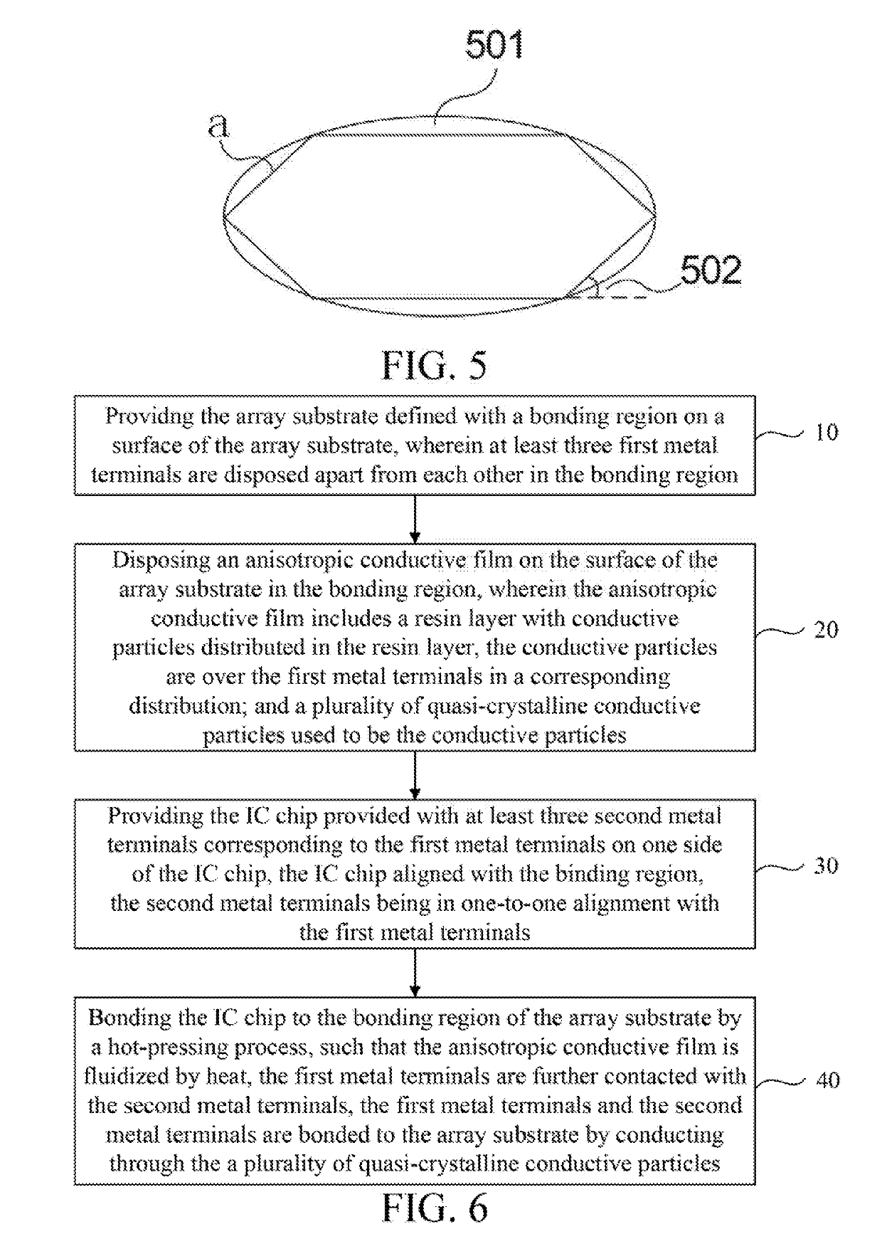
[0029]The following description of each embodiment refers to the appended drawings for illustrating specific embodiments in which the present disclosure may be practiced. Directional terms as mentioned in the present disclosure, such as “up”, “down”, “front”, “post”, “left”, “right”, “inside”, “outside”, “lateral”, etc., are merely used for the purpose of illustrating and understanding the present disclosure and are not intended to be limiting of the present disclosure. In the drawings, units with similar structures are denoted by the same reference numerals.

[0030]The present disclosure is directed at the process in the prior art of bonding the IC chip of a display panel, the conductive particles distributed in a set location of the resin are affected by the fluidity of the resin resulting in positional shifts, then to cause a phenomenon of a short-circuiting in the bump, thereby affecting the quality of the display panel. This defect will be solved in this embodiment of the present...


PUM


Abstract

A display device is provided in the present disclosure, which has a plurality of conductive particles in a packaging region to form an electrical connection between a plurality of first metal terminals on a surface of an array substrate and a plurality of second metal terminals on a surface of an IC chip after the array substrate and the IC chip are pressed to be bonded through a conductive adhesive. At least three of the conductive particles are distributed between the first metal terminals and the second metal terminals. A plurality of quasi-crystalline conductive particles are used to be the conductive particles.

Description

FIELD OF DISCLOSURE[0001]The present disclosure relates to a technical field of displays, and particularly to a display device and a method for bonding an array substrate and an IC chip.BACKGROUND OF DISCLOSURE[0002]In a module manufacturing process for a display panel, it is required to bond an integrated circuit (IC) chip and a substrate. Current bonding methods are mainly achieved by pasting an anisotropic conductive film (ACF) on one end of a bump (which is a metal protrusion) to be bonded, and thermal pressing the other end of the bump on the ACF, and then completing a bonding process after a curing process.[0003]Prior to thermal pressing the IC chip and the substrate, a plurality of conductive particles of the anisotropic conductive film are distributed in a resin. During the thermal pressing process, because the temperature raises to increase fluidity of the resin layer, the conducting particles, touching the bump, are forced into a gap due to bonding pressure, density of the...

Claims


Application Information

Patent Timeline
IPC IPC(8): H01L51/56H01L51/52H01L51/00C09J9/02
CPCH01L51/56H01L51/5237H01L51/0097C09J9/02H01L2251/5338H01L2924/14H01L2224/29499H01L2224/83203H01L2224/2929H01L2224/83851H01L24/29H01L24/83H10K71/421H01L2924/00012H01L24/81H01L24/14H01L24/06H01L25/0657H01L24/17H01L24/12H10K50/84H10K71/00H10K77/111H10K2102/311
Inventor LL, CHENG
Owner WUHAN CHINA STAR OPTOELECTRONICS SEMICON DISPLAY TECH CO LTD
Learn More