Rotor for a Motor

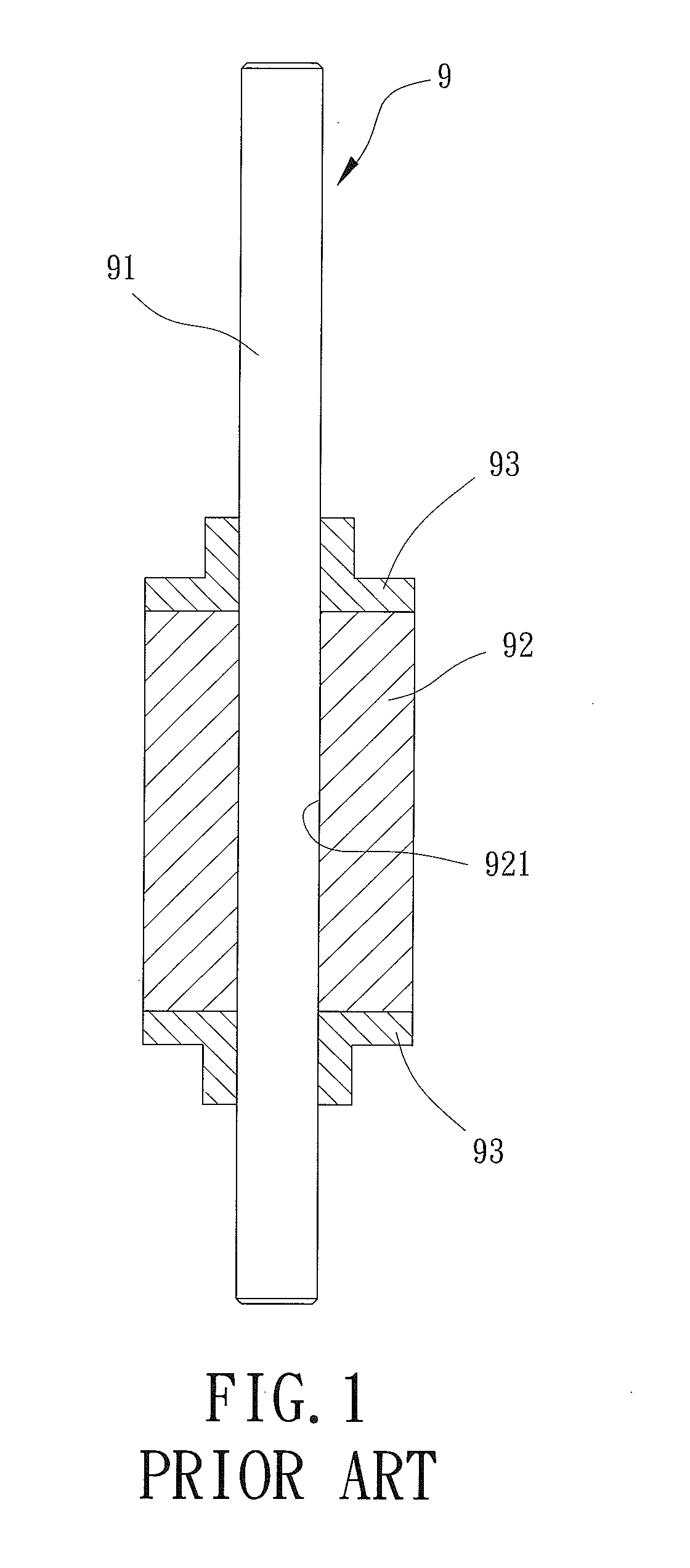
a rotor and motor technology, applied in the direction of dynamo-electric machines, magnetic circuit rotating parts, magnetic circuit shape/form/construction, etc., can solve the problems of unstable rotation, shaft and magnetic member cannot be securely coupled with each other, and the magnetic member can break under the press fitting between the shaft and the magnetic member, etc., to achieve convenient and efficient assembly, reinforce the engagement, and fast alignment

Inactive Publication Date: 2019-05-02
SUNONWEALTH ELECTRIC MACHINE IND
View PDF4 Cites 3 Cited by
  • Summary
  • Abstract
  • Description
  • Claims
  • Application Information

AI Technical Summary

Benefits of technology

[0024]In an example, each of two ends of the permanent magnet spaced from each other in the axial direction includes a first engagement portion. Each of the two engaging units includes a second engagement portion at one of two ends of the engaging unit facing the permanent magnet. Thus, the second engagement portion of each engaging unit can engage with the first engagement portion of a respective end of the permanent magnet, thereby reinforcing the engagement between the engaging units and the permanent magnet while permitting fast alignment between the positioning holes of each engaging unit and the through-holes of the elastic sleeve. Accordingly, the convenient and efficient assembly can be attained.
[0025]In an example, one of the first and second engagement portions is in a U shape and another of the first and second engagement portions is in the form of a U-shaped protrusion to permit the first and second engagement portions to be engaged with each other in the axial direction. Accordingly, the convenient and efficient assembly can be attained.
[0026]In an example, the permanent magnet is an anisotropic magnet. Thus, the structure of the rotor of the motor can be simplified, attaining convenient and efficient assembly.
[0027]In an example, each of the two engaging units includes a recess on an outer periphery thereof facing away from the elastic sleeve. Accordingly, the rotational balance of the motor can be improved.
[0028]In an example, each of the two engaging units includes a plurality of notches on an outer periphery thereof. Accordingly, the rotational balance of the motor can be improved.
[0029]In an example, each of the two engaging units is made of copper, aluminum or magnetically insulating steel. Thus, the stability of the magnetism of the rotor can be improved.

Problems solved by technology

However, the magnetic member can break under the press fitting between the shaft and the magnetic member.
Also, the shaft and the magnetic member cannot be securely coupled with each other under the use of the bonding blocks.
Therefore, the currently available rotor often causes some issues such as unstable rotation, low operational efficiency and noise of the motor.
Thus, the entire motor generates vibration during the operation, such that not only the noise is generated but also the operation of the motor is unsmooth and the service life of the motor is shortened.

Method used


Image

  • Rotor for a Motor
  • Rotor for a Motor
  • Rotor for a Motor

Examples


first embodiment

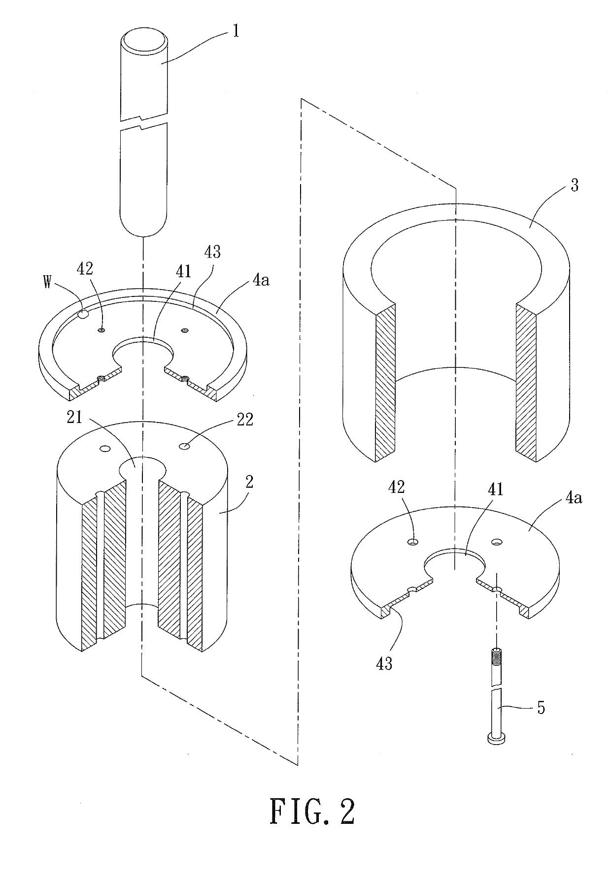
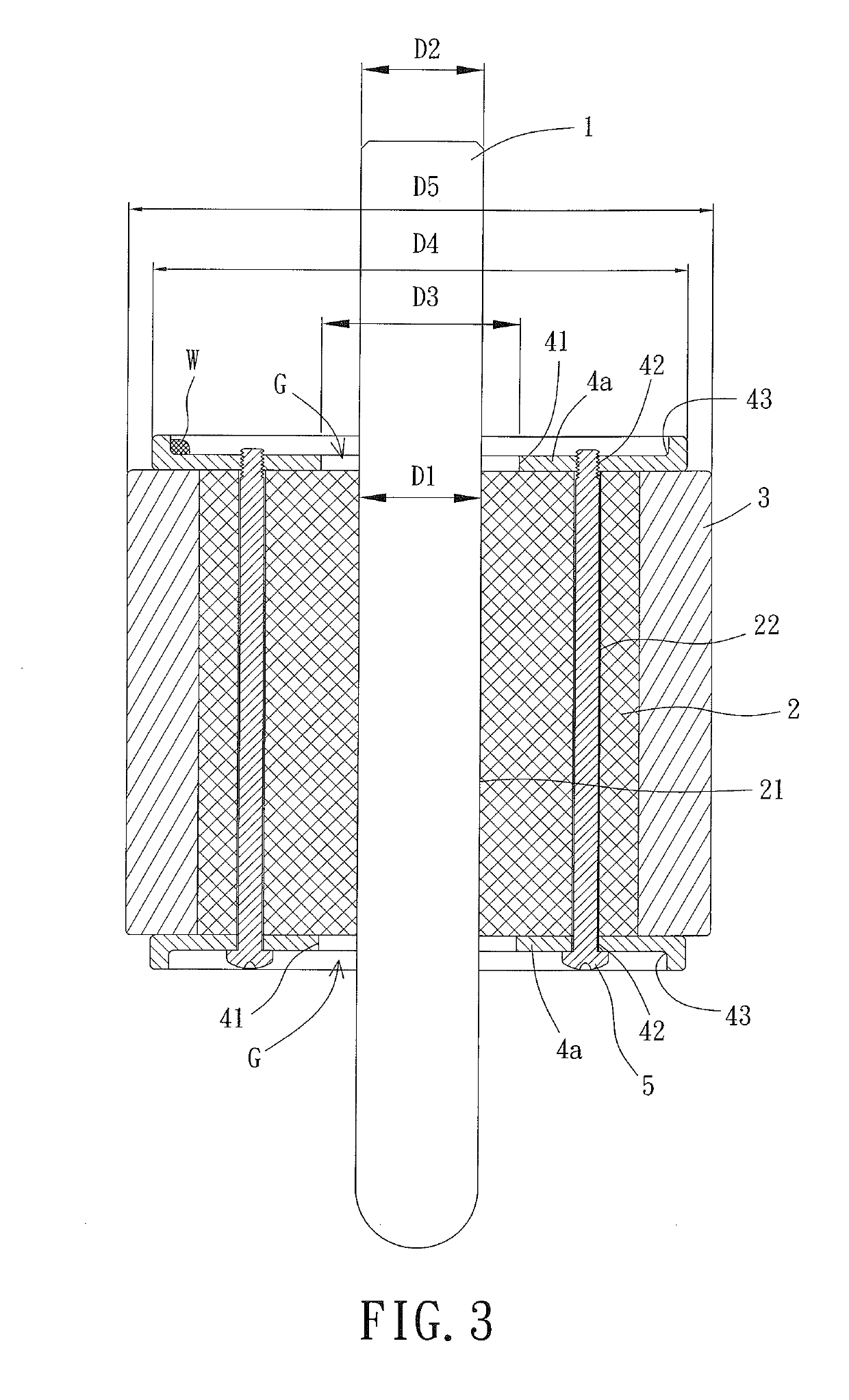
[0040]FIGS. 2 and 3 show a rotor for a motor according to the invention. The rotor includes a shaft 1, an elastic sleeve 2, a permanent magnet 3 and two engaging units 4a. The elastic sleeve 2 and the permanent magnet 3 are mounted around the shaft 1 and are clamped between the two engaging units 4a.

[0041]The rotor according to the invention is used in an inner-rotor motor. The shaft 1 is rotatably mounted on a base of the motor. During the operation of the inner-rotor motor, the shaft 1 of the rotor can rotate relative to the base of the motor.

[0042]The elastic sleeve 2 is fit around an outer periphery of the shaft 1. In this embodiment, the elastic sleeve 2 abuts with the outer periphery of the shaft 1. The elastic sleeve 2 is made of an elastomeric material such as rubber or silica gel. The elastic sleeve 2 includes a shaft hole 21 through which the shaft 1 extends. In a preferred case, a diameter D1 of the shaft hole 21 is smaller than a diameter D2 of the shaft 1 before assemb...

third embodiment

[0052]FIG. 6 shows a rotor for a motor according to the invention where two engaging units 4c are adhered to the two ends of the elastic sleeve 2, respectively. It is worth mentioning that each of the two ends of the elastic sleeve 2 is provided with a positioning protrusion 23 in this embodiment. Each of the two engaging units 4c is fit around the positioning protrusion 23 via the through-hole 41 to ensure that the two engaging units 4c can be properly mounted to the two ends of the elastic sleeve 2 without making contact with the shaft 1 during the assembly of the engaging units 4c. As a result, the assembly efficiency of the rotor can be improved and the effect in reducing the vibration transmitted from the elastic sleeve 2 to the shaft 1 can be improved.

[0053]FIG. 7 shows a rotor for a motor according to a fourth embodiment of the invention. The fourth embodiment of the invention is substantially the same as the first embodiment except for the outlines of two engaging units 4d a...


PUM


Abstract

A rotor for a motor according to the invention is provided to solve the problem where the rotor of the conventional motor does not have an excellent vibration-reducing effect. The rotor for the motor includes a shaft, an elastic sleeve, a permanent magnet and two engaging units. The elastic sleeve is fit around the shaft. The permanent magnet is fit around the elastic sleeve. The elastic sleeve and the permanent magnet have two sides spaced from each other in an axial direction. The two engaging units are coupled with the elastic sleeve and the permanent magnet at the two sides, respectively. Each of the two engaging units includes a through-hole through which the shaft extends. The two engaging units are not in contact with the shaft.

Description

CROSS REFERENCE TO RELATED APPLICATION[0001]The application claims the benefit of Taiwan application serial No. 106137171, filed on Oct. 27, 2017, and the contents of which are incorporated herein by reference.BACKGROUND OF THE INVENTION1. Field of the Invention[0002]The present invention generally relates to a rotor for a motor and, more particularly, to a rotor for use in an inner-rotor motor.2. Description of the Related Art[0003]In early times, the rotor used in an inner-rotor motor includes a shaft and a magnetic member. The magnetic member is press fit around the shaft or fixed to the shaft via a plurality of bonding blocks, permitting the shaft to rotate jointly with the magnetic member. An example of such a rotor is disclosed in Taiwan Patent No. 1572125 and U.S. Patent Publication No. 2007 / 0273227.[0004]However, the magnetic member can break under the press fitting between the shaft and the magnetic member. Also, the shaft and the magnetic member cannot be securely coupled ...

Claims


Application Information

Patent Timeline
Patent Type & Authority Applications(United States)
IPC IPC(8): H02K1/27H02K1/28H02K15/03H02K21/14
CPCH02K1/2713H02K1/28H02K15/03H02K21/14H02K1/2733
Inventor HORNG, ALEXWU, CHIH-MINGHSIAO, CHIA-WEI
Owner SUNONWEALTH ELECTRIC MACHINE IND
Why Eureka
Try Eureka