Aircraft landing gear
- Summary
- Abstract
- Description
- Claims
- Application Information
AI Technical Summary
Benefits of technology
Problems solved by technology
Method used
Image

Examples
Embodiment Construction
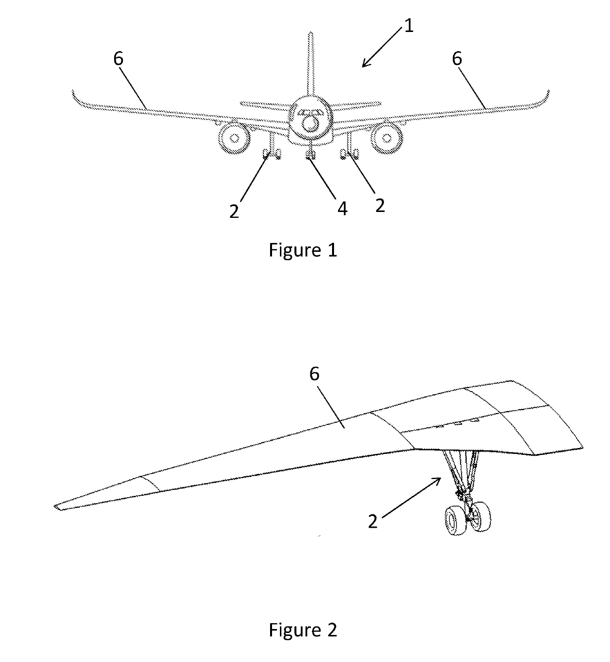
[0065]FIG. 1 shows an aircraft 1 including a main landing gear 2 in accordance with a first example embodiment of the invention. The aircraft 1 includes a nose landing gear 4, located at the centre line of the aircraft, and two main landing gear 2, one main landing gear being mounted on each wing 6. FIG. 2 shows a perspective view of a portion of a wing 6 including a landing gear 2 in accordance with the first example embodiment. In FIG. 2 the landing gear 2 is in a deployed configuration.
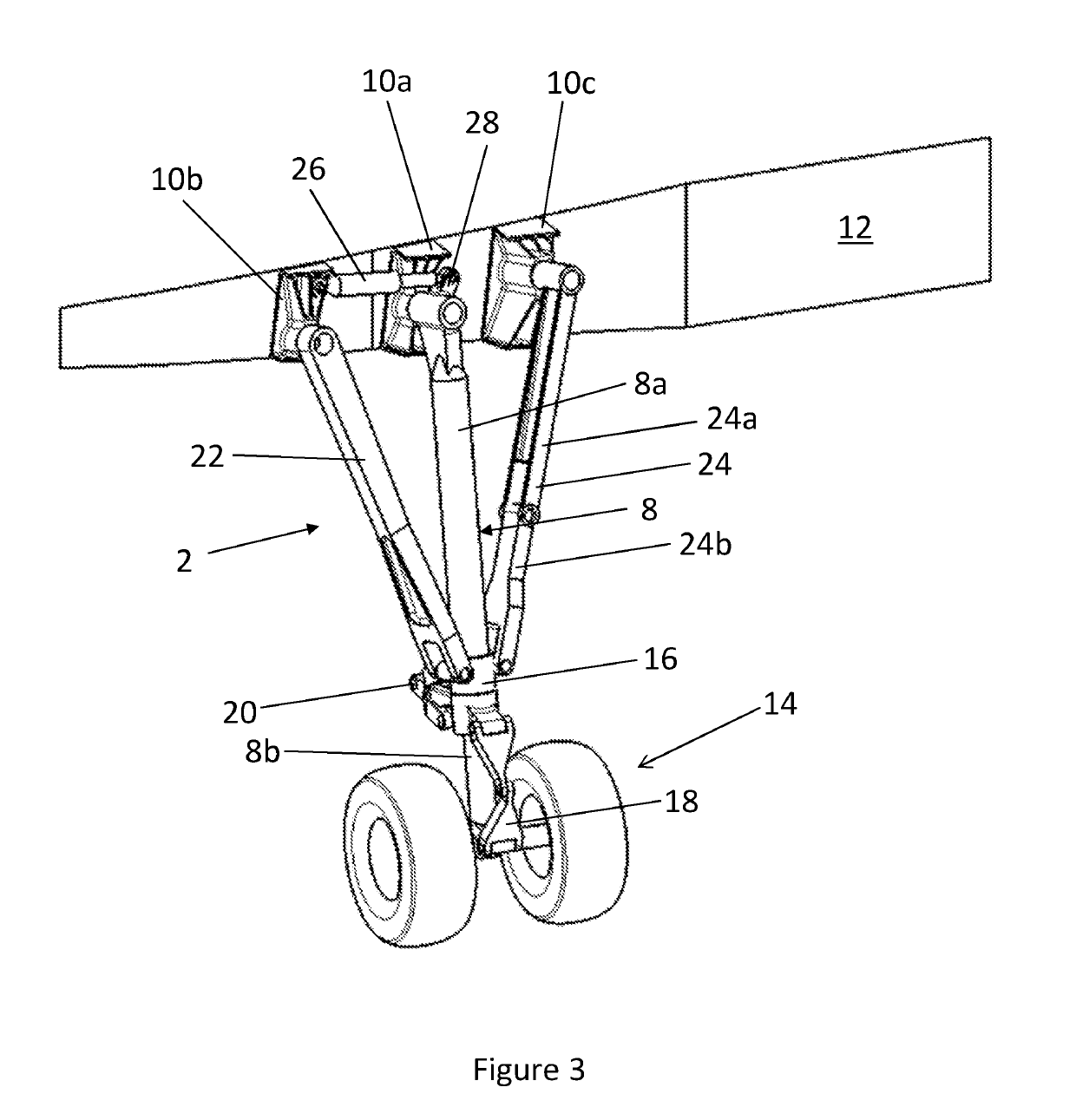
[0066]FIG. 3 shows a close-up of the landing gear of FIG. 2 and a portion of the rear spar 12 of the wing 6 of FIG. 2. The landing gear 2 comprises an oleo strut 8, comprising a housing 8a and a piston 8b. The housing 8a is connected at its upper end to a central attachment point 10a, the central attachment point 10a being fixed to the rear spar 12 of the wing 6. A two-wheel axle 14 is connected to the lower end of the piston 8b. A cylindrical collar 16 is mounted on the housing 8a of the strut 8. ...
PUM
 Abstract
Description
Claims
Application Information