
Method for improving the display state of liquid crystal panel, liquid crystal panel, and liquid crystal display

a liquid crystal display and display state technology, applied in the field of display technology, can solve the problems of not meeting the needs of users, neither side of the module whitening phenomenon, nor the frame brightness uneven (mura) and achieve the effect of improving the brightness of the lcd panel box and improving the experien

Active Publication Date: 2019-05-09
WUHAN CHINA STAR OPTOELECTRONICS TECH CO LTD
View PDF0 Cites 0 Cited by
  • Summary
  • Abstract
  • Description
  • Claims
  • Application Information

AI Technical Summary

Benefits of technology

This patent discloses a method to improve the display of a liquid crystal panel. The technical problem addressed is that multiple sub-pixels on the panel can generate white light on both sides, resulting in poor display quality. The method involves adjusting the storage capacitance value of specific sub-pixels to reduce voltage drops and improve display quality. The technical effect of this method is improved display quality of liquid crystal panels.

Problems solved by technology

In the 20th century, the image display, the cathode ray tube (CRT) occupies an absolute dominance, with the development of display technology, CRT monitors because of the size is too large and huge consumption of energy consumption and other factors, can not meet the needs of users.
In general, TFT (Thin Film Transistor) LCD liquid crystal panel in the manufacture and drive process, if there is plastic box plastic pollution, liquid crystal vapor or module drive design defects and other issues, will lead to the frame brightness uneven (Mura) or both sides of the module whitening phenomenon.

Method used


Image

  • Method for improving the display state of liquid crystal panel, liquid crystal panel, and liquid crystal display
  • Method for improving the display state of liquid crystal panel, liquid crystal panel, and liquid crystal display
  • Method for improving the display state of liquid crystal panel, liquid crystal panel, and liquid crystal display

Examples


Embodiment Construction

[0037]The present disclosure will now be described in detail with reference to the accompanying drawings and examples.

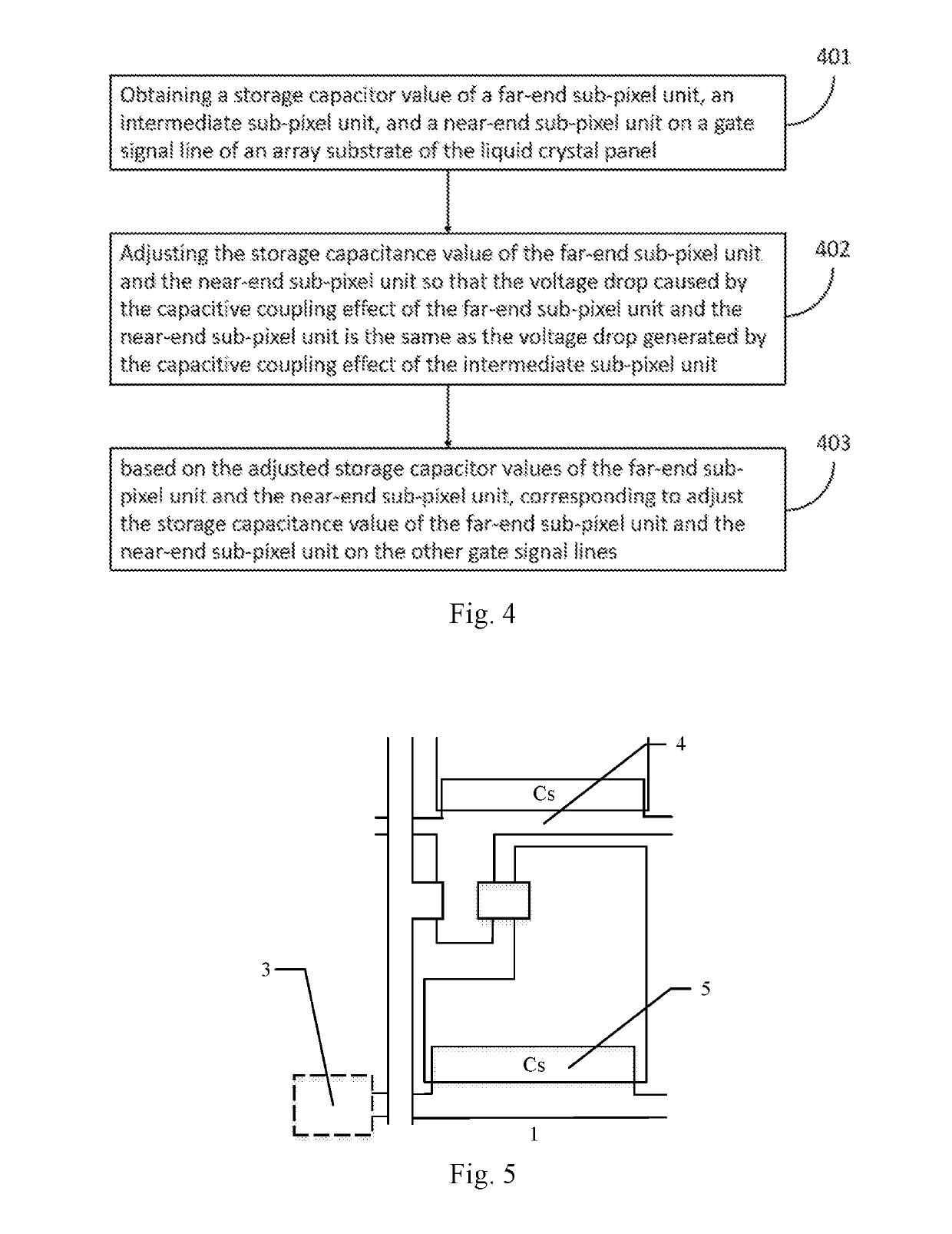
[0038]Refer to FIG. 4, FIG. 4 is a flow diagram of an embodiment of a method for improving the display state of a liquid crystal panel of the present disclosure, the method for improving the liquid crystal panel of the present embodiment includes the steps of:

[0039]401: Obtaining a storage capacitor value of a far-end sub-pixel unit, an intermediate sub-pixel unit, and a near-end sub-pixel unit on a gate signal line of an array substrate of the liquid crystal panel;

[0040]In the present embodiment, the far-end sub-pixel unit, the intermediate sub-pixel unit, and the near-side sub-pixel unit are divided into the far-end sub-pixel unit region, the intermediate sub-pixel cell region, and the near-end sub-pixel cell region along the same gate signal line. The specific step of obtaining a storage capacitor value of a far-end sub-pixel unit, an intermediate sub-pixel unit, ...


PUM

PropertyMeasurementUnit
storage capacitoraaaaaaaaaa
storage capacitanceaaaaaaaaaa
dielectric constantaaaaaaaaaa

Abstract

The present disclosure discloses a method for improving the display state of a liquid crystal panel, the method including: obtaining a storage capacitor value of a far-end sub-pixel unit, an intermediate sub-pixel unit, and a near-end sub-pixel unit on a gate signal line of an array substrate of the liquid crystal panel; adjusting the storage capacitance value so that the voltage drop caused by the capacitive coupling effect of the far-end sub-pixel unit and the near-end sub-pixel unit is the same as the voltage drop generated by the capacitive coupling effect of the intermediate sub-pixel unit; based on the adjusted storage capacitor values corresponding to adjust the storage capacitance value on the other gate signal lines. Through the above-mentioned way, the brightness of the LCD panel frame is improved or the whitening phenomenon on both sides of the module is improved, improving the display quality of the liquid crystal panel.

Description

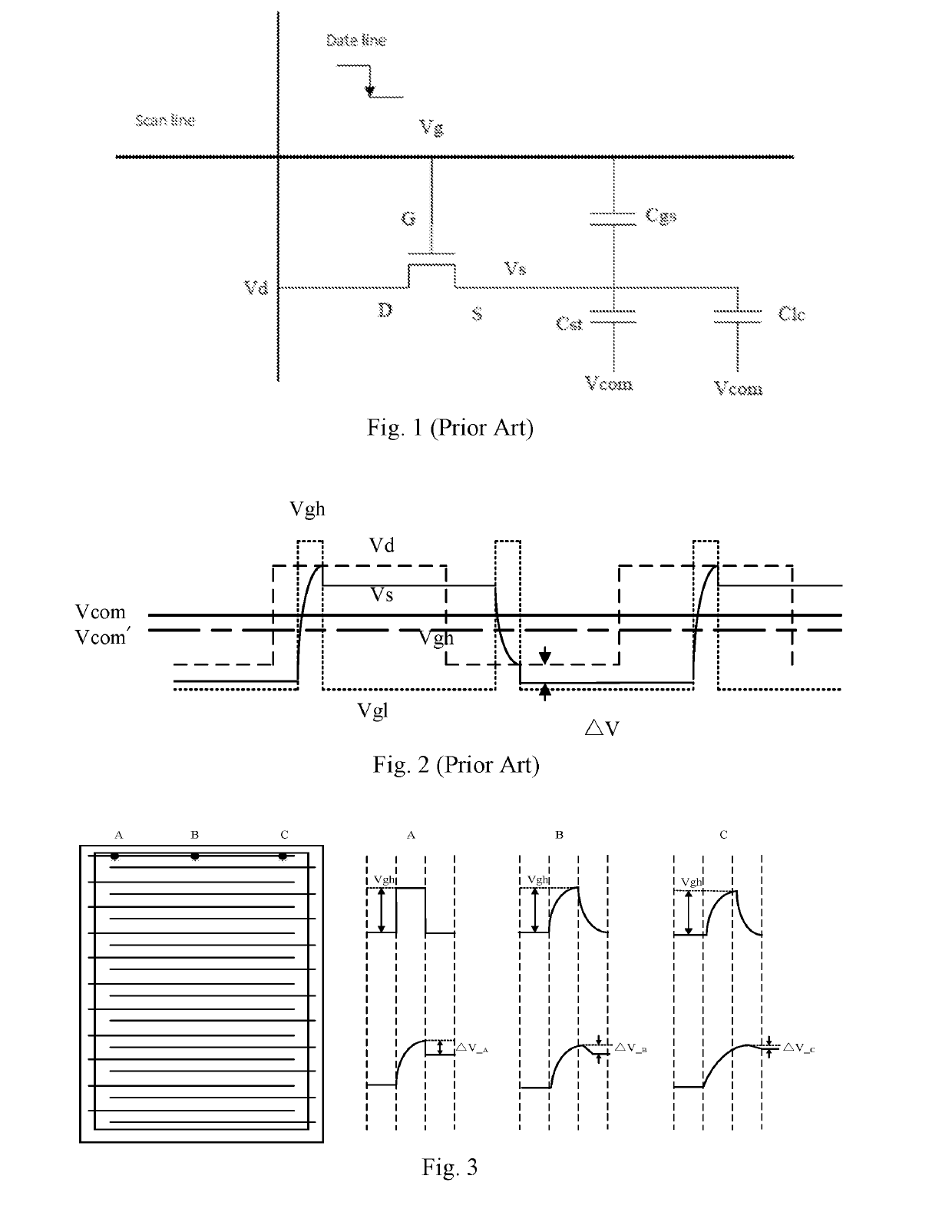
FIELD OF THE DISCLOSURE[0001]The present disclosure relates to a display technology field, and more particularly to a method for improving the display state of a liquid crystal panel, a liquid crystal panel, and a liquid crystal display.BACKGROUND OF THE DISCLOSURE[0002]Information society with the increase in the amount of confidence and frequent information exchange, people will be more, more extensive, more often face a variety of display devices. In other words, the display and display technology has become an indispensable part of people's lives. In the 20th century, the image display, the cathode ray tube (CRT) occupies an absolute dominance, with the development of display technology, CRT monitors because of the size is too large and huge consumption of energy consumption and other factors, can not meet the needs of users. The liquid crystal display (Liquid Crystal Display, LCD) technology is just the development of the current trend of information products.[0003]LCD devices ...

Claims


Application Information

Patent Timeline
Patent Type & Authority Applications(United States)
IPC IPC(8): G02F1/133G02F1/1362G09G3/36
CPCG02F1/13306G02F1/136286G02F1/136213H01L27/124G09G2300/0819G09G2320/0233G09G3/3677G09G3/36H01L27/1255G09G2320/0223
Inventor XING, ZHENZHOUZUO, QINGCHENG
Owner WUHAN CHINA STAR OPTOELECTRONICS TECH CO LTD
Learn More