
Display panel and display device

A display panel and substrate technology, which is applied in the direction of semiconductor devices, electrical components, circuits, etc., can solve the problems of inability to detect changes in light intensity in real time, and OLED display devices cannot reach the best display state, and achieve the effect of improving the display state.

Active Publication Date: 2021-03-05
BOE TECH GRP CO LTD
View PDF3 Cites 0 Cited by
  • Summary
  • Abstract
  • Description
  • Claims
  • Application Information

AI Technical Summary

Problems solved by technology

However, this compensation method cannot detect the light intensity change of each sub-pixel in real time, resulting in the failure of the OLED display device to reach the best display state.

Method used


Image

  • Display panel and display device
  • Display panel and display device
  • Display panel and display device

Examples


Embodiment Construction

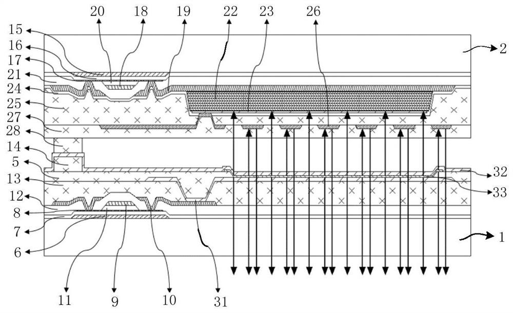
[0028] In order for those skilled in the art to better understand the technical solution of the present invention, the display panel and the display device provided by the present invention will be described in detail below with reference to the accompanying drawings.

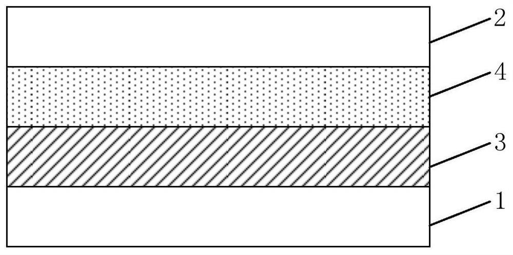
[0029] figure 1 A schematic structural diagram of a display panel provided in Embodiment 1 of the present invention, as shown in figure 1 As shown, the display panel includes a first substrate 1 and a second substrate 2 oppositely arranged, and a side of the first substrate 1 close to the second substrate 2 is provided with a plurality of sub-pixel units 3, and a side of the second substrate 2 close to the first One side of the substrate 1 is provided with a plurality of photodetection units 4, and the photodetection units 4 are arranged corresponding to the sub-pixel units 3, and the photodetection units 4 are used to acquire the light signals emitted by the corresponding sub-pixel units 3, and transmit the li...


PUM


Abstract

The invention discloses a display panel and a display device. The display panel includes a first base and a second base that are oppositely arranged, and a side of the first base close to the second base is provided with a plurality of sub-pixel units, and a side of the second base close to the first base A plurality of photodetection units are arranged on one side, and the photodetection units are arranged correspondingly to the sub-pixel units; The signal is converted into an electrical signal. The display panel and the display device provided by the present invention can detect the light intensity change of the sub-pixel in real time, and compensate the sub-pixel in real time, so as to achieve the purpose of improving the display state of the display device.

Description

technical field [0001] The present invention relates to the field of display technology, in particular to a display panel and a display device. Background technique [0002] In the manufacture of organic light-emitting diode (OLED) display devices, especially oxide organic light-emitting diode (OxideOLED) display devices, in addition to designing the compensation circuit inside the pixel, it is usually necessary to use charge-coupled The device (CCD) performs a precise optical calibration at the pixel (pixel) level, performs external electrical compensation of the pixel circuit, and compensates for the offset of the threshold voltage (Vth). However, this compensation method cannot detect the light intensity change of each sub-pixel in real time, so that the OLED display device cannot reach an optimal display state. Contents of the invention [0003] The present invention aims to solve at least one of the technical problems in the above-mentioned prior art, and provides a ...

Claims


Application Information

Patent Timeline
Patent Type & Authority Patents(China)
IPC IPC(8): H01L27/32H01L51/52
CPCH10K59/60H10K59/127H10K59/13H10K50/86
Inventor 李东升王路吴慧利贺芳尹东升黎午升姚琪赵伟利于美娜张丽蕾
Owner BOE TECH GRP CO LTD
Learn More