
Fully autonomous vehicle lift

a fully autonomous, vehicle technology, applied in the direction of lifting frames, lifting devices, etc., can solve the problems of service technicians who may also sustain immediate or long-lasting injuries, vehicle damage, safety concerns, etc., to reduce the amount of time it takes to rack and eliminate any risk of injury

Inactive Publication Date: 2019-05-16
FORD GLOBAL TECH LLC
View PDF7 Cites 8 Cited by
  • Summary
  • Abstract
  • Description
  • Claims
  • Application Information

AI Technical Summary

Benefits of technology

The invention is a system for lifting vehicles off the floor for servicing. The system is automatic, meaning the lift arms are placed correctly before the vehicle is lifted off. This can be used with fixed or retractable systems. The system reduces the time it takes to prepare a vehicle for lifting and ensures safety by minimizing the risk of injury.

Problems solved by technology

Vehicle stability while it is off the ground is a critical requirement for the safety of the service technicians as vehicle instability can lead to a vehicle falling off a two-post lift.
It is more common for novice technicians to improperly place lift arms which results in a safety concern and the possibility of vehicle damage.
While manually placing the lift arms, the service technician may also sustain immediate or long lasting injuries.
Over years of performing vehicle maintenance that requires lifting a vehicle off the ground, bending over and getting on the hands and knees on the concrete shop floor can result in injuries.
While adding a larger drive motor decreases the amount of time it takes to raise and lower a vehicle, this approach does not address the time consuming process needed to place lift arms.
Accordingly, known approaches to lifting a vehicle for service do not produce satisfactory results.
The current approach to lifting a vehicle can present a safety risk to servicing technicians, result in vehicle damage, and include a time consuming process to place lift arms.

Method used


Image

  • Fully autonomous vehicle lift
  • Fully autonomous vehicle lift
  • Fully autonomous vehicle lift

Examples


Embodiment Construction

[0030]In the following figures, the same reference numerals will be used to refer to the same components. In the following description, various operating parameters and components are described for different constructed embodiments. These specific parameters and components are included as examples and are not meant to be limiting.

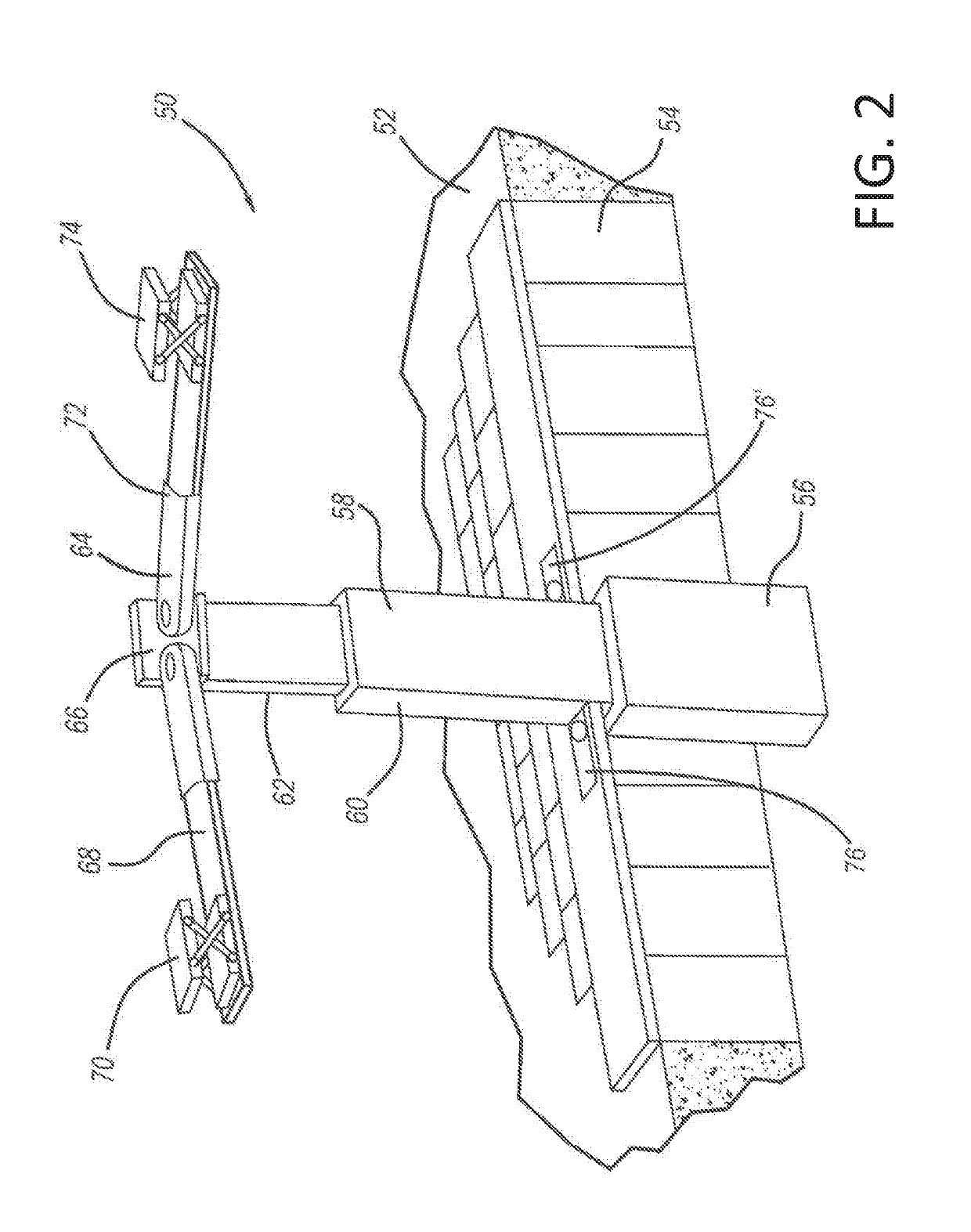
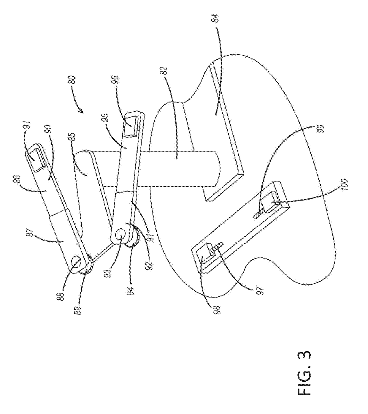
[0031]The accompanying figures and the associated description illustrate the autonomous vehicle lift system of the disclosed inventive concept. Alternative versions of the vehicle lift system are illustrated as are alternative version of the lift arms. It is to be understood that the illustrated embodiments are suggestive as the shapes of, for example, the vertical posts and the lift arms, may be adopted without deviating from the spirit or scope of the disclosed inventive concept.

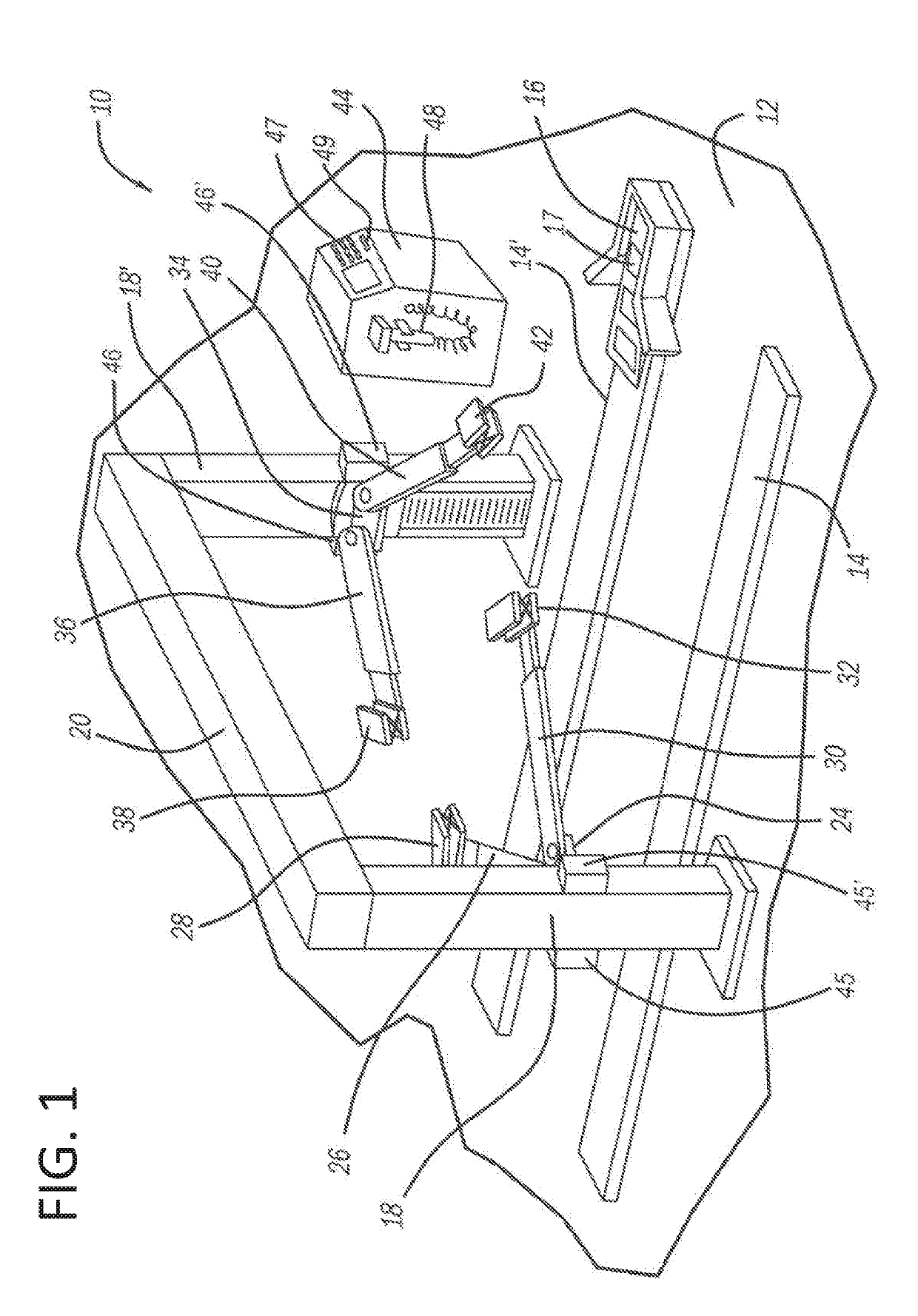
[0032]Referring to FIG. 1, a perspective view of an embodiment of the autonomous vehicle lift system of the disclosed concept is shown. The lift system, generally illustrated as 1...


PUM


Abstract

The disclosed inventive concept provides an autonomous vehicle lift system in which the lift arms are automatically placed into their correct positions prior to the vehicle being lifted for servicing. The system includes a pair of spaced apart vertical posts and a wheel locator. Each post is fitted with a vertically movable lift arm assembly. Each lift arm assembly includes a pair of independently operating lift arms and drive systems for both rotating the arm into position and for extending the arm. At the end of each lift arm is a lift pad. Each lift pad may include a scissors system for lifting and lowering the pad relative to the associated arm. An operator's station is provided for inputting vehicle information. Once the information is entered, the autonomous lift system is initiated. The lift arms automatically move into their correct predetermined positions and the vehicle is ready to be lifted.

Description

TECHNICAL FIELD[0001]The disclosed inventive concept relates to a lift system for a vehicle. More particularly, the disclosed inventive concept relates to a lift system for a vehicle that operates autonomously to locate lift pads under predetermined lift points of a given vehicle. Once the vehicle is placed in position relative to the lift, the operator needs only to input vehicle identification information and initiate the drive system. After the system is initiated, the lift arms and the lift pads are moved autonomously into position and the lifting operation commences.BACKGROUND OF THE INVENTION[0002]Vehicles ordinarily require a variety of services during their operating lifetimes. Some services, such as oil changes, can be performed with the vehicle on a floor of a shop in which a pit is formed in the floor. The oil changers work from the sub-surface pit and thus no vertical movement of the vehicle is necessary. Other under-hood services can also be performed while the vehicle ...

Claims


Application Information

Patent Timeline
Patent Type & Authority Applications(United States)
IPC IPC(8): B66F7/28B66F7/06B66F3/46
CPCB66F7/28B66F7/065B66F3/46B66F2700/123B66F7/0666B66F7/20
Inventor BARTOS, GREG
Owner FORD GLOBAL TECH LLC
Learn More