Gas turbine engine having an air-oil heat exchanger

a technology of heat exchanger and gas turbine engine, which is applied in the direction of engines, efficient propulsion technologies, mechanical equipment, etc., can solve the problems of large amount of heat being transferred to the oil, engine propulsive fan has demanding cooling requirements, and engine oil cooling can be compromised, so as to avoid specific fuel consumption penalties, simple devices, and high power

Active Publication Date: 2019-05-16
ROLLS ROYCE PLC
View PDF9 Cites 2 Cited by
  • Summary
  • Abstract
  • Description
  • Claims
  • Application Information

AI Technical Summary

Benefits of technology

[0015]Thus the deflector provides a means to generate sufficient pressure difference across the heat exchanger at low power engine operating conditions, such as ground idle. The deflector can be a relatively simple device that avoids the disadvantages of the alternative strategies discussed above. Moreover, by being movable to the stowed position it can avoid incurring a specific fuel consumption penalty at cruise, and higher power, operating conditions.

Problems solved by technology

This results in a large amount of heat being transferred to the oil.
In a geared turbofan engine, for example, the power gearbox which transfers power to the engine's propulsive fan has demanding cooling requirements.
Without an adequate differential, cooling of the engine oil can be compromised.
However, even when such steps are taken there is a risk at low power engine operating conditions (e.g. ground idle) of a pressure gradient being generated along the core fairing which does not provide an adequate pressure drop across the heat exchanger to drive air through it.
However, the core zone ventilation nozzle is generally less aerodynamically efficient than the “cold nozzle” at the end of the bypass duct.
Also exhausting the cooling air to the core zone ventilation nozzle may be unattractive due to the amount of additional of ducting that would be required.
However, this can produce additional noise, and would also require complicated additional ducting.

Method used


Image

  • Gas turbine engine having an air-oil heat exchanger
  • Gas turbine engine having an air-oil heat exchanger

Examples


Embodiment Construction

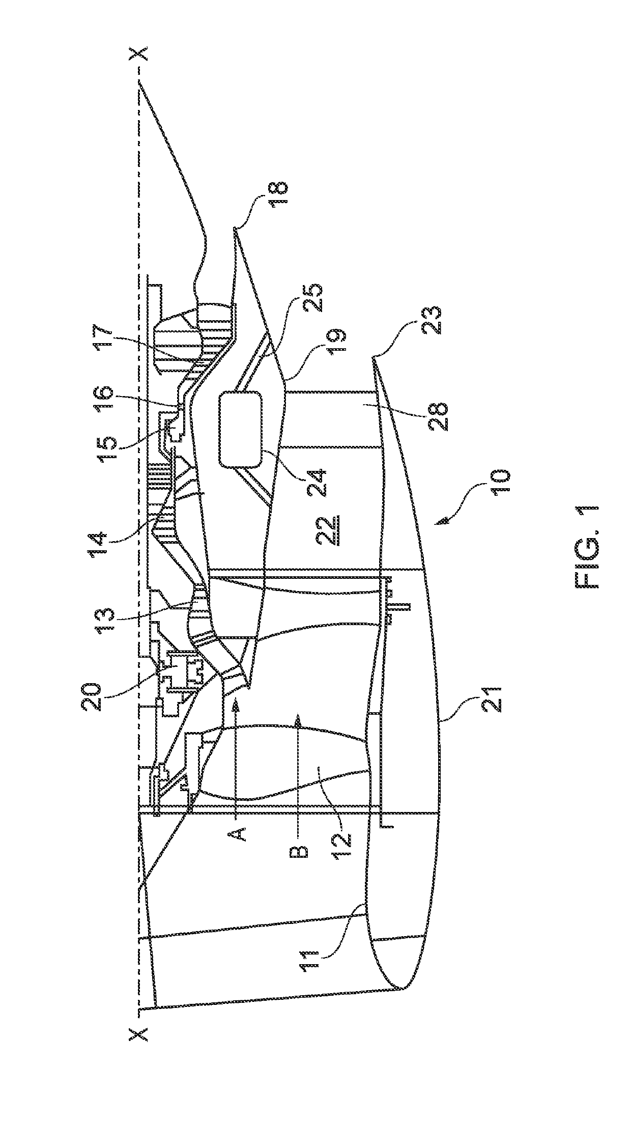
[0028]With reference to FIG. 1, a geared turbofan gas turbine engine is generally indicated at 10 and has a principal and rotational axis X-X. The engine comprises, in axial flow series, an air intake 11, a propulsive fan 12, a low pressure compressor 13, a high-pressure compressor 14, combustion equipment 15, a high-pressure turbine 16, a low-pressure turbine 17 and a core engine exhaust nozzle 18. A core fairing 19 surrounds the core engine from the low pressure compressor 13 to the exhaust nozzle 18. A nacelle 21 generally surrounds the engine 10 and defines the intake 11, a bypass duct 22 and a bypass exhaust nozzle 23.

[0029]During operation, air entering the intake 11 is accelerated by the fan 12 to produce two air flows: a first air flow A into the low-pressure compressor 13 and a second air flow B which passes through the bypass duct 22 to provide propulsive thrust. The low-pressure compressor 13 compresses the air flow A directed into it before delivering that air to the hig...


PUM


Abstract

A gas turbine engine includes: a core engine surrounded by a core fairing; a propulsive fan; a nacelle surrounding the propulsive fan, the core fairing and the core engine; and a fan duct for receiving a bypass air flow accelerated by the propulsive fan, the fan duct being defined between the nacelle and the core fairing. The gas turbine engine further includes an air-oil heat exchanger for cooling engine oil using an air flow diverted from the bypass air flow, the heat exchanger being mounted behind a wall of the fan duct. The gas turbine engine further includes a flow passage which receives the diverted air flow at a first location in the fan duct, delivers the diverted air flow to the heat exchanger, and returns the diverted air flow to the fan duct at a second location which is downstream of the first location.

Description

CROSS-REFERENCE TO RELATED APPLICATIONS[0001]This specification is based upon and claims the benefit of priority from UK Patent Application Number GB 1718796.4 filed on Nov. 14, 2017, the entire contents of which are incorporated herein by reference.BACKGROUNDField of the Disclosure[0002]The present disclosure relates to a gas turbine engine having an air-oil heat exchanger.Description of the Related Art[0003]Oil is used in gas turbine engines to lubricate and cool electrical generators, bearings and gears in the transmission system. This results in a large amount of heat being transferred to the oil. In order to maintain the oil, and the components that the oil is cooling, at acceptable temperatures, it is necessary to remove this heat.[0004]In a geared turbofan engine, for example, the power gearbox which transfers power to the engine's propulsive fan has demanding cooling requirements. One approach for managing the temperature of the engine's lubricating oil is to mount one or mo...

Claims


Application Information

Patent Timeline
Patent Type & Authority Applications(United States)
IPC IPC(8): F02C7/141F01D17/10
CPCF02C7/141F01D17/105F05D2260/20F01D25/12F02C7/18F02C9/18F02K3/075F05D2260/606Y02T50/60
Inventor HOLT, JAMES
Owner ROLLS ROYCE PLC
Why Eureka
Try Eureka