Piezoelectric vibrating piece and piezoelectric device

Inactive Publication Date: 2019-05-16
NIHON DEMPA KOGYO CO LTD
View PDF0 Cites 2 Cited by
  • Summary
  • Abstract
  • Description
  • Claims
  • Application Information

AI Technical Summary

Benefits of technology

The patent describes a piezoelectric vibrating piece that has a thin, convex shape around its edges, which reduces unnecessary vibration and confines the vibration energy. This design helps improve the performance of the vibrating piece, but it also increases labor and cost in the manufacturing process.

Problems solved by technology

However, forming the piezoelectric substrate into the convex shape causes a problem of labor and cost increase in processing.
However, even when the inclined surface shape as described in Japanese Unexamined Patent Application Publication No. 2002-217675 is formed, it has been found that the effect that reduces an unnecessary vibration substantially differs depending on dimensions of the inclined-surface shape.
That is, there has been a problem where simply forming the peripheral area of the excitation electrode in an inclined-surface shape does not ensure the sufficiently reduced unnecessary vibration.

Method used


Image

  • Piezoelectric vibrating piece and piezoelectric device
  • Piezoelectric vibrating piece and piezoelectric device
  • Piezoelectric vibrating piece and piezoelectric device

Examples


Embodiment Construction

[0026]The embodiments of this disclosure will be described in detail with reference to the drawings. The embodiments in the following description do not limit the scope of the disclosure unless otherwise stated.

[0027][AT-Cut]

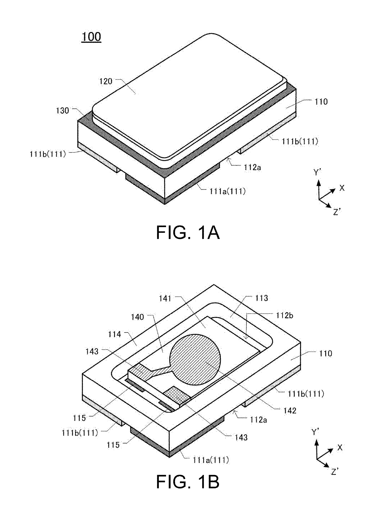
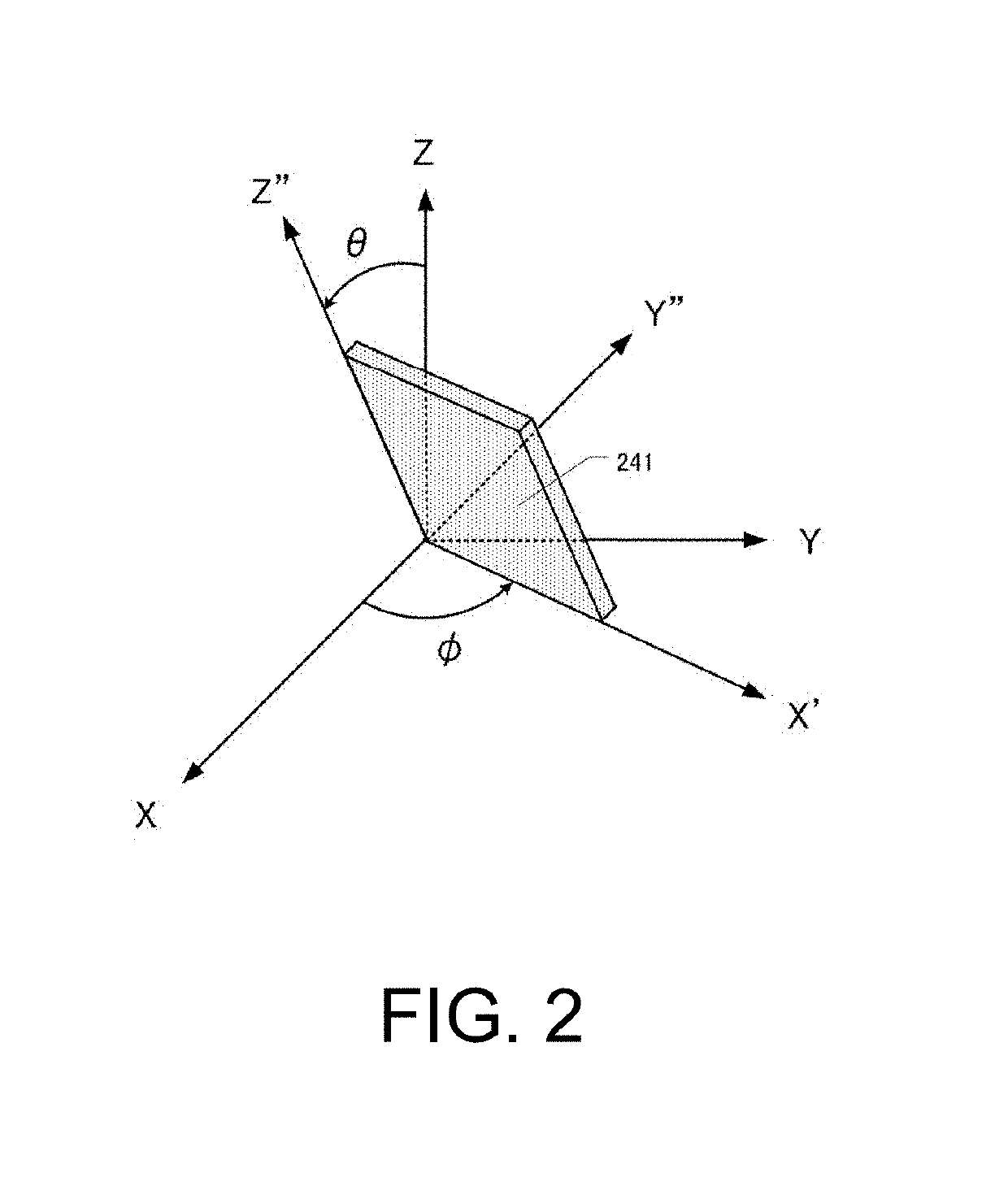
[0028]FIG. 1A is a perspective view of a piezoelectric device 100. The piezoelectric device 100 includes, mainly, a base 110, a lid 120, and a piezoelectric vibrating piece 140 (see FIG. 1B) that vibrates at a predetermined vibration frequency. An outer shape of the piezoelectric device 100 is formed in, for example, an approximately rectangular parallelepiped shape. The piezoelectric vibrating piece 140 is formed using an AT-cut quartz-crystal material that vibrates in a thickness-shear vibration mode as a base material. The AT-cut quartz-crystal material is formed having a principal surface (XZ surface) that is rotated by 35° 15′ from a Z-axis toward a −Y-axis direction around an X-axis with respect to a Y-axis of crystallographic axes (XYZ). In the following ...


PUM


Abstract

A piezoelectric vibrating piece includes a piezoelectric substrate and excitation electrodes. The piezoelectric substrate is formed in a flat plate shape and vibrates in a thickness-shear vibration mode. The excitation electrodes are formed on respective both principal surfaces of the piezoelectric substrate and each include a main thickness portion and a flat portion. The main thickness portion has a first thickness. The flat portion is formed in a peripheral area of the main thickness portion and has a second thickness that is thinner than the first thickness between from a portion contacting the main thickness portion to an outermost periphery of the excitation electrode, extends from the portion contacting the main thickness portion to the outermost periphery of the excitation electrode, and has a width formed to have a length of 0.63 times or more and 1.88 times or less of a flexural wavelength of an unnecessary vibration.

Description

CROSS-REFERENCE TO RELATED APPLICATIONS[0001]This application is based on and claims priority under 35 U.S.C. § 119 to Japanese Patent Application No. 2017-221018, filed on Nov. 16, 2017, and Japanese Patent Application No. 2018-155923, filed on Aug. 23, 2018, and the entire contents of which are incorporated herein by reference.TECHNICAL FIELD[0002]This disclosure relates to a piezoelectric vibrating piece including an inclined portion in a peripheral area of an excitation electrode and relates to a piezoelectric device.DESCRIPTION OF THE RELATED ART[0003]A piezoelectric vibrating piece, which includes an excitation electrode on a piezoelectric substrate, is formed in a convex shape having a thin thickness in a peripheral area of the piezoelectric substrate, and thus confines a vibration energy, thereby ensuring reduced unnecessary vibration. However, forming the piezoelectric substrate into the convex shape causes a problem of labor and cost increase in processing.[0004]In contras...

Claims


Application Information

Patent Timeline
IPC IPC(8): H03H9/13H03H9/02H03H9/10H03H9/19
CPCH03H9/132H03H9/02023H03H9/105H03H9/19H03H9/02157H03H9/1021H03H9/131
Inventor KAGA, SHIGETAKANAKAHARA, MASAAKI
Owner NIHON DEMPA KOGYO CO LTD
Why Eureka
Try Eureka