
Support structure for a wind turbine blade

a support structure and wind turbine technology, applied in wind energy generation, climate sustainability, engine fuctions, etc., can solve the problems of uneven support of wind turbine blades during storage and transportation, risk of damaging the wind turbine blade, and uneven load of belt elements, so as to reduce uneven load and increase the service life of belt elements

Active Publication Date: 2019-05-23
SIEMENS GAMESA RENEWABLE ENERGY AS
View PDF4 Cites 0 Cited by
  • Summary
  • Abstract
  • Description
  • Claims
  • Application Information

AI Technical Summary

Benefits of technology

The patent text describes a new support structure for wind turbine blades that is simple and reliable. This structure aims to reduce the need for manual handling and adjustment of the blades, which can save time, money, and prevent damage to the blades.

Problems solved by technology

Today, the weight of wind turbine blades during storage and transportation may not be supported evenly in the transport and storage equipment.
As a consequence, the load is not evenly distributed to all of the cross slings.
When the load of the wind turbine blade is not evenly distributed in the storage and transportation equipment, a risk of damaging the wind turbine blade may occur.
However, this may not be an easy task, since the technician cannot measure the tension in each cross sling.
Hence, it may not be ensured a perfectly distributed load.
Furthermore, if the wind turbine blade starts to move due to dynamic loading, the system may not adapt to this new load scenario and the wind turbine blade may be locally overloaded.
Additionally, it may be challenging that each wind turbine blade type has different shapes and sizes, which may require individual equipment being fitted to the exact wind turbine blade geometry.
The repair costs for damages of the wind turbine blades during storage and transportation as well as the costs for handling and adjusting the current storage system add to the total costs of the wind turbine blade.

Method used


Image

  • Support structure for a wind turbine blade
  • Support structure for a wind turbine blade
  • Support structure for a wind turbine blade

Examples


Embodiment Construction

[0079]The illustrations in the drawings are schematically. It is noted that in different figures, similar or identical elements are provided with the same reference signs.

[0080]FIG. 1 to FIG. 4 shown one exemplary embodiment of the present invention.

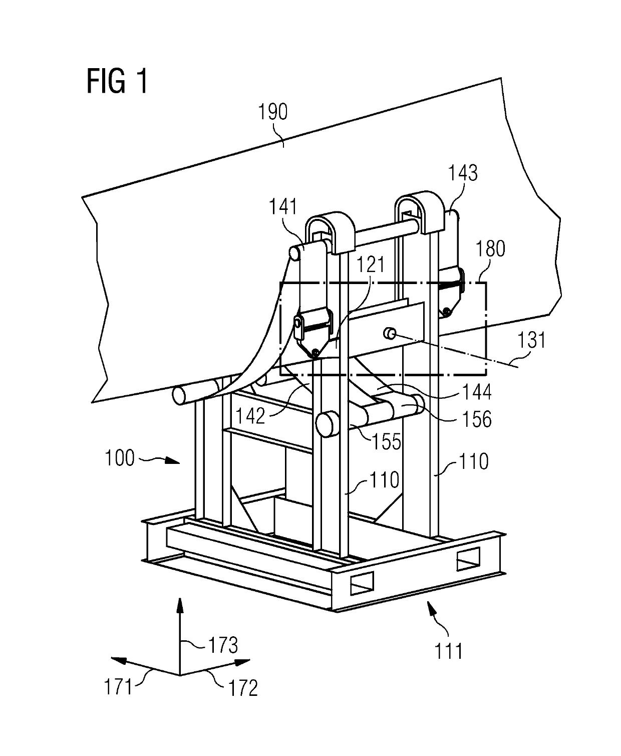
[0081]FIG. 1 shows a perspective view of the first section 111 of the support structure 100 supporting a wind turbine blade 190 according to an exemplary embodiment.

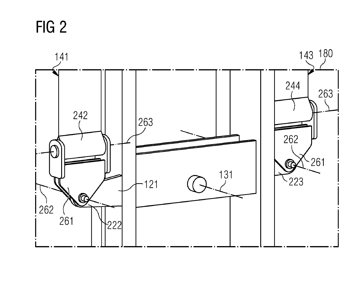
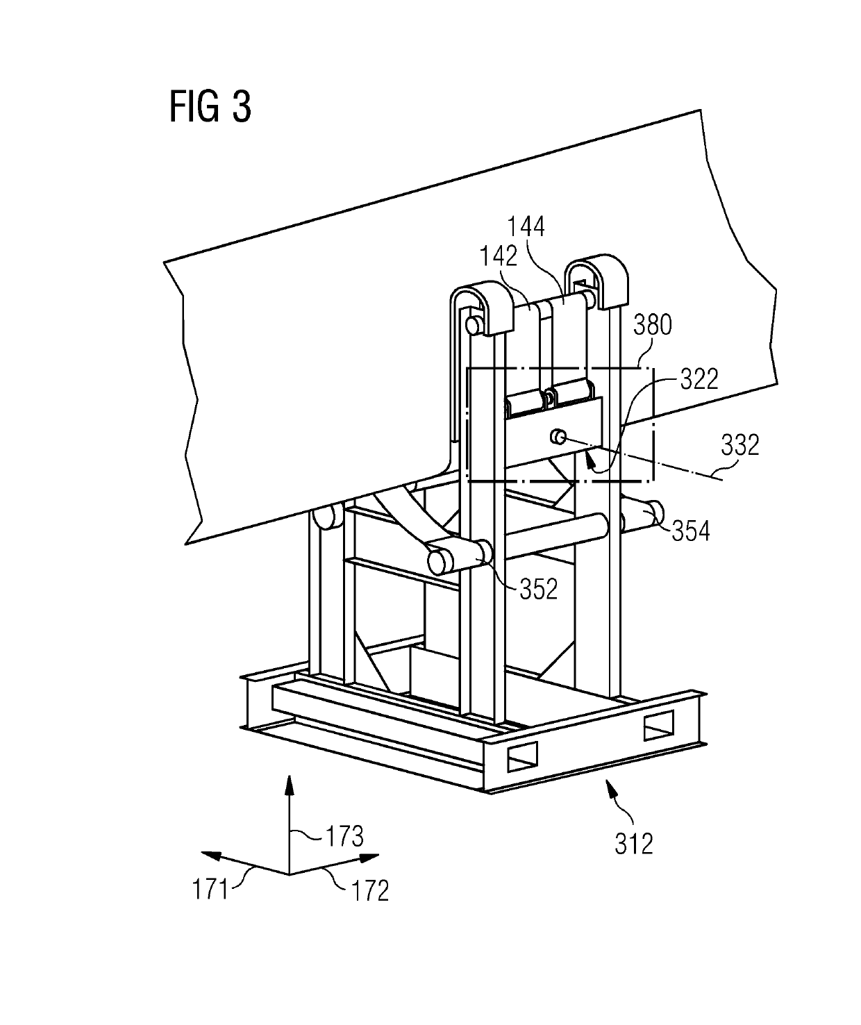
[0082]The first seesaw element 121 is pivotably fixed to the first section 111 of the frame structure 110 by a first pivoting axis 131. A section of the wind turbine blade 190 is arranged in-between the first section 111 and the second section 312 (shown in detail in FIG. 3). The first belt element 141 and the third belt element 143 are fixed to two spaced apart ends of the first seesaw element 121. The longitudinal extension of the first seesaw element 121 extends along the second direction 172. The second end 155 of the second belt element 142 is fixed to the first section ...


PUM


Abstract

Provided is a support structure for a wind turbine blade and a method for manufacturing a support structure for a wind turbine blade The support structure includes a frame structure including a first section and a second section which are spaced apart with respect to each other along a first direction such that a section of a wind turbine blade is arrangeable in-between the first section and the second section. The support structure further includes two seesaw elements being pivotably fixed to a respective section and having a respective pivoting axis parallel to the first direction and four belt elements being fixed with their respective first end to a respective end of the respective seesaw element Furthermore, a respective second end of the respective belt element are each fixed to the respective other section of the frame structure

Description

CROSS REFERENCE TO RELATED APPLICATIONS[0001]This application claims priority to European application 17202862.3 having a filing date of Nov. 21, 2017, the entire contents of which are hereby incorporated by reference.FIELD OF TECHNOLOGY[0002]The following relates to the field of decreasing damages and hence costs during long-term storage of turbine blades and increasing the flexibility of supporting different blade types. Particularly, the present embodiments of the invention relates to a support structure for a wind turbine blade and a method for manufacturing a support structure for a wind turbine blade.BACKGROUND[0003]In current storage and transportation solutions for wind turbine blades, a complex clamping equipment for storage and transportation is used. Furthermore, up till now, there were developed individual transport and storage equipment for every different wind turbine blade size.[0004]Today, the weight of wind turbine blades during storage and transportation may not be...

Claims


Application Information

Patent Timeline
Patent Type & Authority Applications(United States)
IPC IPC(8): F03D13/40
CPCF03D13/40F05B2260/02F05B2230/60B66C1/108F03D13/20Y02E10/728Y02P70/50Y02E10/72
Inventor ANDRESEN, PETERZAREBA, WITOLD
Owner SIEMENS GAMESA RENEWABLE ENERGY AS
Learn More