Methods, systems, apparatuses and devices for facilitating motion analysis in an environment

a technology of motion analysis and environment, applied in the field of data processing, can solve the problems of reducing resolution and reducing sensitivity

Active Publication Date: 2019-05-23
RELIANCE CORE CONSULTING LLC
View PDF50 Cites 28 Cited by
  • Summary
  • Abstract
  • Description
  • Claims
  • Application Information

AI Technical Summary

Benefits of technology

[0014]This summary is provided to introduce a selection of concepts in a simplified form, that are further described below in the Detailed Description. This summary is not intended to identify key features or essential features of the claimed subject matter. Nor is this summary intended to be used to limit the claimed subject matter's scope.

Problems solved by technology

1. At a sensor layer, the trends in constructing video cameras are to move to higher and higher pixel density in order to improve the image resolution. Increasing the resolution diminishes the sensitivity. But sensitivity is the property needed to detect changes of contrast in the observed scene and especially in dim light. The move to high sensitivity leads to using detectors that work each as an independent pixel that count photons. High sensitivity requires to develop large fields of view, a move that diminishes the resolution.
2. At the telecommunication layer, each video camera produces a compressed bit rate of several megabits per second (Mb / s) that has to be transmitted in real time, or stored but not yet analyzed to detect motion. For example, compressing HD video with an original sampling resolution of 1920×1080 pixels using an MPEG4 standard with a constant frame rate of 24, 25 or 30 progressive images per second (image / s) generates bitrates that range from 5,000 to 10,000 Kbit / s. The file-size of the compressed video may range from about 400 MB to 750 MB (MegaBytes) after 10 minutes and 6 times those amounts after one hour.
3. At the application layer, all video information still need to be analyzed in real time to unfold the embedded motion.

Method used


Image

  • Methods, systems, apparatuses and devices for facilitating motion analysis in an environment
  • Methods, systems, apparatuses and devices for facilitating motion analysis in an environment
  • Methods, systems, apparatuses and devices for facilitating motion analysis in an environment

Examples


Embodiment Construction

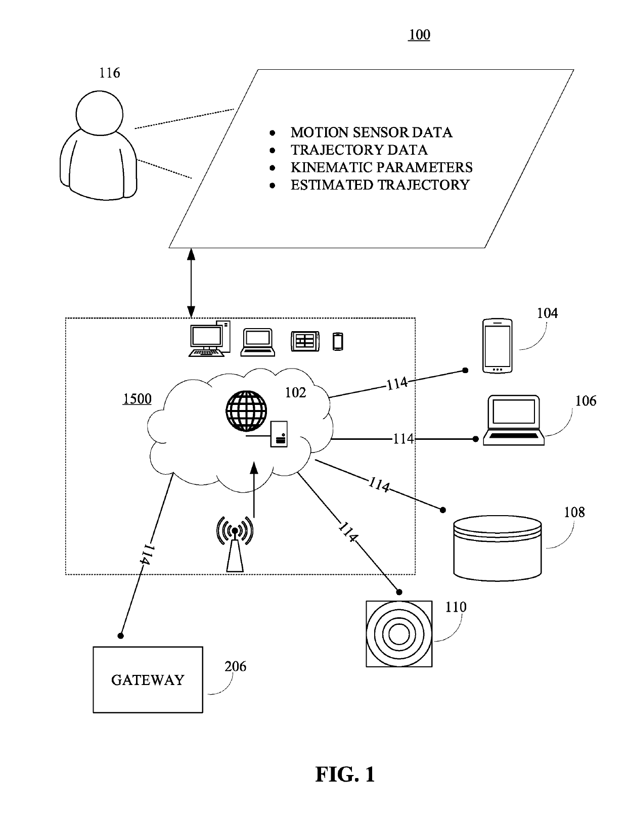
[0034]As a preliminary matter, it will readily be understood by one having ordinary skill in the relevant art that the present disclosure has broad utility and application. As should be understood, any embodiment may incorporate only one or a plurality of the above-disclosed aspects of the disclosure and may further incorporate only one or a plurality of the above-disclosed features. Furthermore, any embodiment discussed and identified as being “preferred” is considered to be part of a best mode contemplated for carrying out the embodiments of the present disclosure. Other embodiments also may be discussed for additional illustrative purposes in providing a full and enabling disclosure. Moreover, many embodiments, such as adaptations, variations, modifications, and equivalent arrangements, will be implicitly disclosed by the embodiments described herein and fall within the scope of the present disclosure.

[0035]Accordingly, while embodiments are described herein in detail in relation...


PUM


Abstract

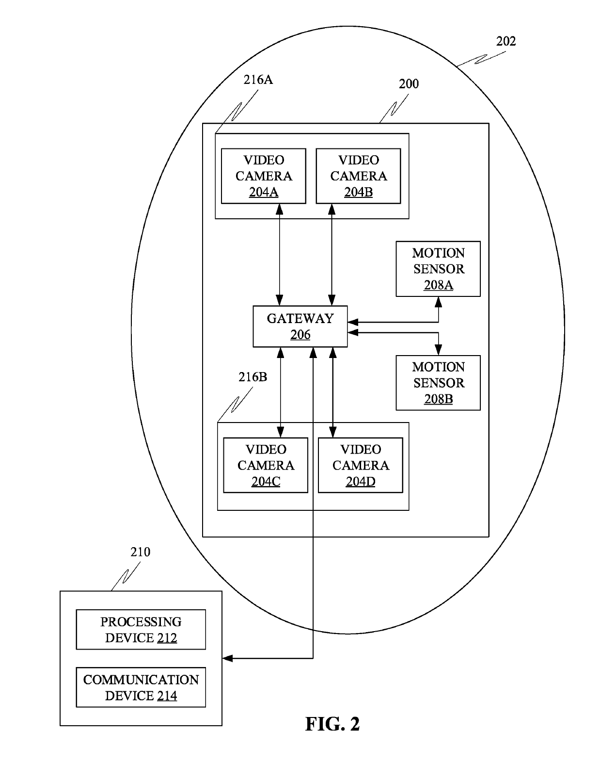
Disclosed herein is a system for facilitating motion analysis in an environment, in accordance with some embodiments. Accordingly, the system may include a plurality of motions sensors configured to be disposed in the environment. Further, the plurality of motion sensors may be configured to generate a plurality of motion data corresponding to at least one motion of at least one object in the environment. Further, the system may include a plurality of video cameras disposable at a plurality of key locations in the environment. Further, at least one video camera may be configured to transmit a part of a corresponding image sequence to a remote monitoring center through at least one gateway. Further, the system may include at least one gateway disposable proximal to the environment, which may be configured as a two-way interface capable of communicating with the remote monitoring center and the plurality of motion sensors.

Description

[0001]The current application is a continuation-in-part (CIP) application of a U.S non-provisional application Ser. No. 16 / 197,725 filed on Nov. 21, 2018. The U.S. non-provisional application 16 / 197,725 claims a priority to a U.S. provisional application Ser. No. 62 / 589,287 filed on Nov. 21, 2017.[0002]The current application also claims a priority to the U.S. Provisional Patent application Ser. No. 62 / 609,594 filed on Dec. 22, 2017.[0003]The current application also claims a priority to the U.S. Provisional Patent application Ser. No. 62,617,502 filed on Jan. 15, 2018.TECHNICAL FIELD[0004]Generally, the present disclosure relates to the field of data processing. More specifically, the present disclosure relates to methods, systems, apparatuses and devices for facilitating motion analysis in an environment.BACKGROUND[0005]Motion analysis may be used for motion detection and / or moving target recognition applications. These applications may include motion analysis in sports fields, mi...

Claims


Application Information

Patent Timeline
Patent Type & Authority Applications(United States)
IPC IPC(8): G06T7/292G06K9/00H04N5/247H04L12/66G06V20/00G06V10/143G06V10/764
CPCG06T7/292G06K9/00771H04N5/247H04L12/66G06T2207/30241G06T2207/20081G06T2207/20092G06T2207/30232G06V20/00G06V20/52G06V20/54G06V10/143G06V10/62G06V10/803G06V10/764G06F18/251H04N7/17318G06F3/0325G06F18/24H04N23/90
Inventor LEDUC, JEAN-PIERRE
Owner RELIANCE CORE CONSULTING LLC
Why Eureka
Try Eureka