Head-mounted display apparatus

a display apparatus and head-mounted technology, applied in the field of display apparatuses, can solve the problems of affecting the visual experience, the pupillary distance adjusting mechanism cannot only synchronously adjust the the existing sight distance adjusting assembly cannot synchronize the sight distance of the left lens barrel, so as to achieve clearer images, convenient adjustment, and effective ensuring the display effect of images

Active Publication Date: 2019-05-23
SHENZHEN KUKU TECH CO LTD
View PDF0 Cites 29 Cited by
  • Summary
  • Abstract
  • Description
  • Claims
  • Application Information

AI Technical Summary

Benefits of technology

[0025]Compared with the prior art, the present invention has the following advantages: in the head-mounted display apparatus provided in this embodiment, by setting the connection structure in the wearing head module, the wearing angle of the display module can be conveniently adjusted. And in the optical module, the left lens barrel mechanism comprises a left lens barrel assembly and a left display screen disposed behind the left lens barrel assembly through the left screen bracket; the right lens barrel mechanism comprises a right lens barrel assembly and a right display screen disposed behind the right lens barrel assembly through the right screen bracket. The optical module adopts the left sight distance adjusting mechanism and the right sight distance adjusting mechanism to respectively adjust the sight distance of the left eye and the right eye, so that users can respectively adjust the sight distance of the left lens barrel assembly and the right lens barrel assembly ac

Problems solved by technology

The existing sight distance adjusting assembly can only synchronously adjust the sight distance of the left lens barrel assembly and the right lens barrel assembly.
For users with different diopters of the left eye and the right eye, synchronously adjusting the sight distance of the left lens barrel assembly and the right lens barrel assembly will cause the image definition seen by the left eye and the right eye to be different when the user views the images through the optical module, thus affecting the visual experience.
The existing pupillary distance adjusting mechanism can only synchronously adjust the distance between the left lens barrel assembly and the right lens barrel as

Method used


Image

  • Head-mounted display apparatus
  • Head-mounted display apparatus
  • Head-mounted display apparatus

Examples


Embodiment Construction

[0044]In order to have a clearer understanding of the technical features, objectives and effects of the present invention, specific embodiments of the present invention will now be described in detail with reference to accompanying drawings.

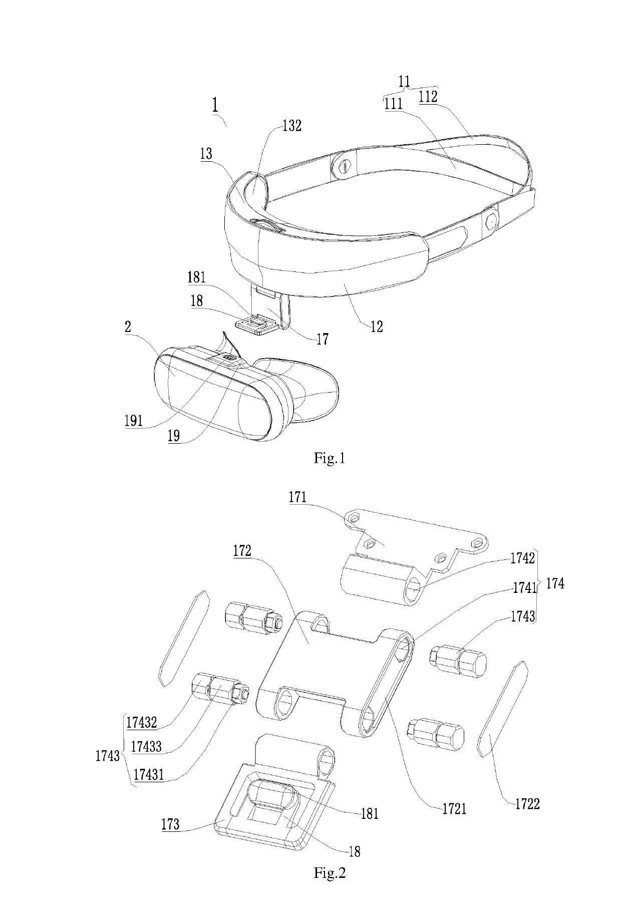
[0045]FIG. 1 shows the head-mounted display apparatus in this embodiment. The head-mounted display apparatus comprises a headband module 1 and a head-mounted display module 2 connected to the headband module 1, wherein the head-mounted display module 2 comprises a head-mounted display module housing and an optical module 3 arranged in the module housing.

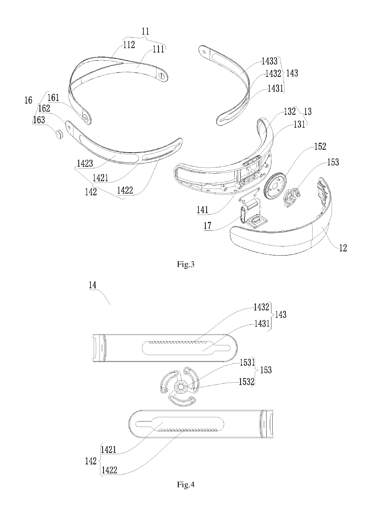
[0046]As shown in FIG. 3, the headband module 1 includes a headband body 11, a front housing 12, a rear housing 13, an elastic adjustment component 14, a control locking component 15, and a connecting structure 17.The head-mounted front housing 12 and the head-mounted rear housing 13 are matched to form an accommodating space. It can be understood that the cushion 132 made of flexible material is ...


PUM


Abstract

The invention discloses a head-mounted display apparatus. The head-mounted display comprises a headband module and a head-mounted display module, wherein the head-mounted display comprises an optical module, the headband comprises a connecting structure connected with the head-mounted display housing so as to adjust the wearing angle of the head-mounted display module; The optical module comprises a module housing, a left lens barrel mechanism, a right lens barrel mechanism, a left sight distance adjusting mechanism and a left pupillary distance adjusting mechanism for adjusting the sight distance and pupillary distance of the left lens barrel mechanism, a right sight distance adjusting mechanism and a right pupillary distance adjusting mechanism for adjusting the sight distance and pupillary distance of the right lens barrel mechanism. The head-mounted display can separately adjust the sight distance and pupillary distance of the left and right lens barrel mechanism, as well as the wearing angle.

Description

CROSS REFERENCE TO RELATED APPLICATIONS[0001]The present application is a Continuation Application of PCT Application No. PCT / CN2016 / 107250 filed on Nov. 25, 2016, which claims the benefit of Chinese Patent Application No. 201610629871.9 filed on Aug. 3, 2016. All the above are hereby incorporated by reference.TECHNICAL FIELD[0002]The invention relates to the field of display apparatus, in particular to the head-mounted display apparatus.BACKGROUND ART[0003]The existing head-mounted display apparatus comprises a head-mounted display module for displaying optical images and a headband module connected with the head-mounted display module, and can be worn on user's head, wherein the head-mounted display module is internally provided with an optical module. The existing optical module comprises a display screen, a left lens barrel assembly and a right lens barrel assembly arranged in front of the display screen, a sight distance adjusting assembly and a pupillary distance adjusting mec...

Claims


Application Information

Patent Timeline
IPC IPC(8): H05K5/02G02B7/12G02B7/02H05K5/00A42B1/24A42B1/22
CPCH05K5/0217G02B7/12G02B7/023H05K5/0017A42B1/24A42B1/22G02B27/0172G02B27/0176G02B7/002G02B2027/0181G02B27/0179G02B2027/0132G02B27/01
Inventor ZHENG, XIAOLINLIU, JUNCHEN, HAO
Owner SHENZHEN KUKU TECH CO LTD
Why Eureka
Try Eureka