

Method and device for straightening a workpiece
a workpiece and straightening technology, applied in the field of straightening workpieces, can solve the problems of requiring comparatively complex devices, affecting the quality of workpieces,
- Summary
- Abstract
- Description
- Claims
- Application Information
AI Technical Summary
Benefits of technology
Problems solved by technology
Method used
Image

Examples
Embodiment Construction
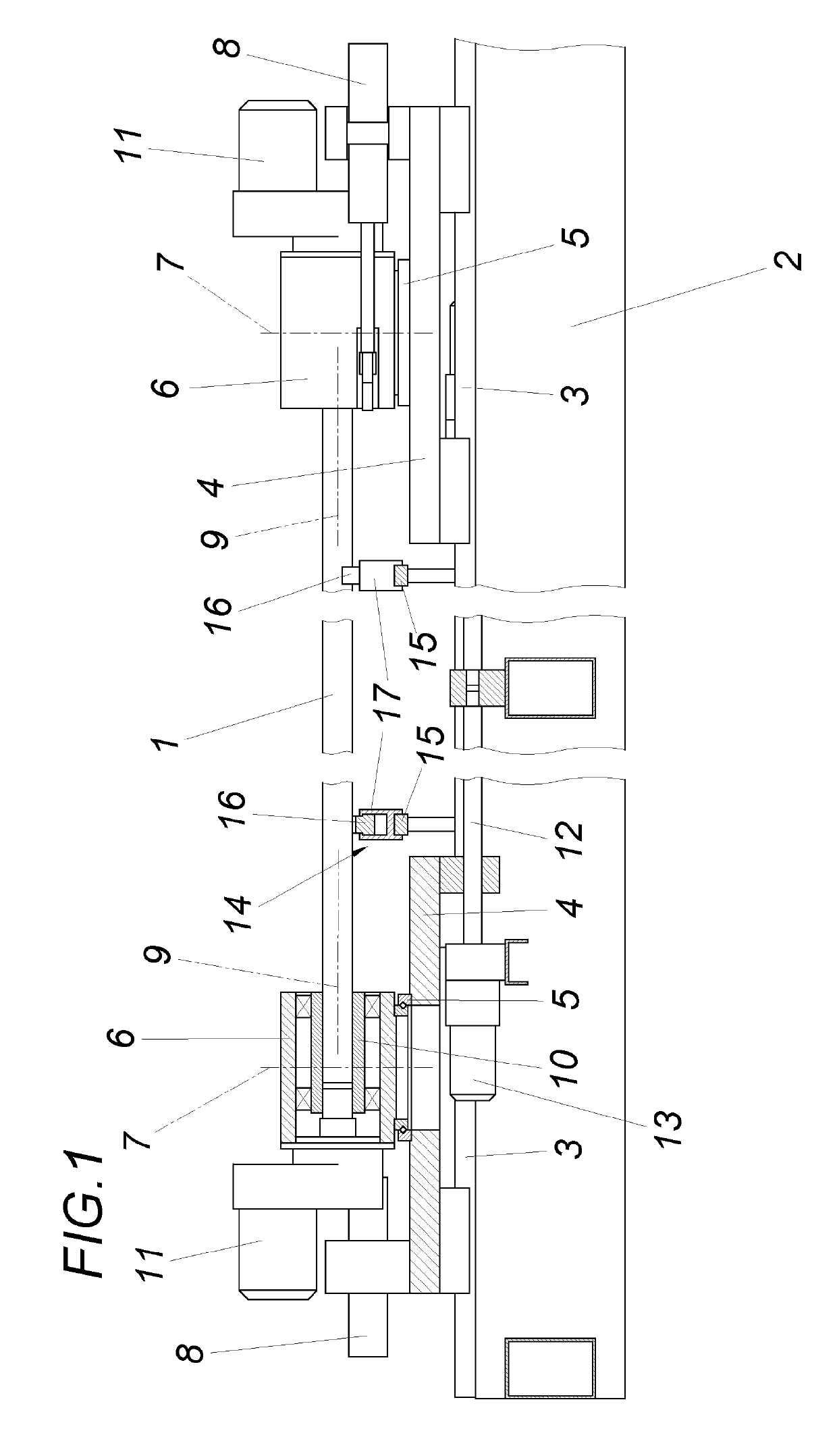
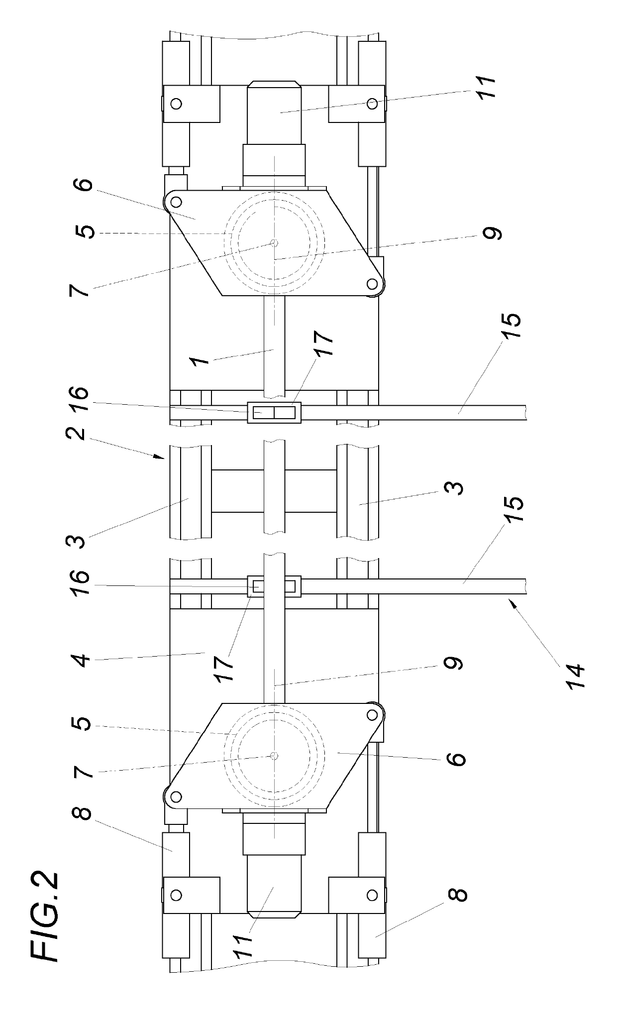
[0003]The invention is therefore based on the object of designing a method for straightening elongated workpieces, in particular of profiles, hollow sections and tubes, such that the required straightening forces can be applied with relatively simple means without risk of surface damage to the workpieces to be straightened.
[0004]Based on a method of the type described, the invention solves the problem in that the workpiece held on the end side in mounting heads is bent out using the mounting heads in directions changing in at least predetermined angular ranges and bent back again.
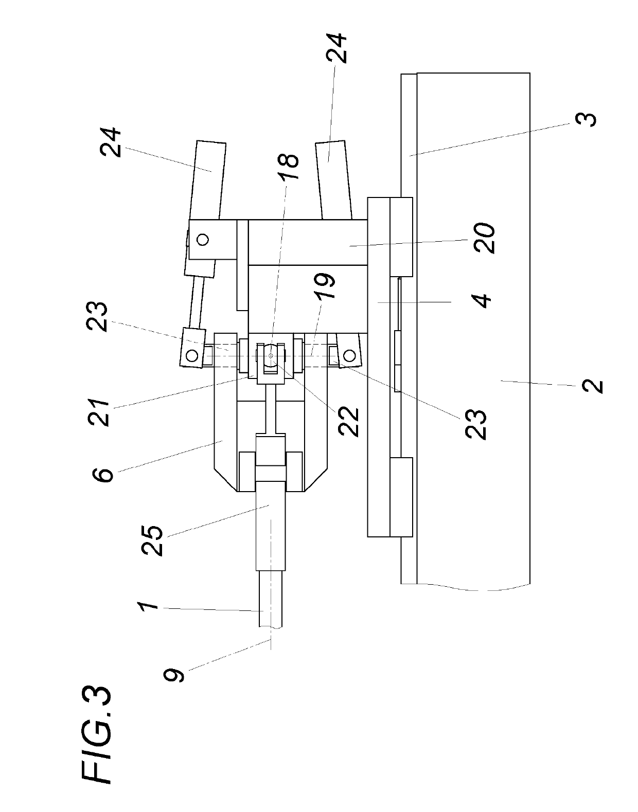
[0005]The invention is based on the finding that in the bending of a workpiece by applying corresponding bending moments in the region of its two longitudinal ends, the workpiece is acted upon over its entire length with an approximately constant bending moment load, so that it is not necessary to apply bending forces in the region between the two longitudinal ends by appropriate straightening tools, as is ...
PUM
| Property | Measurement | Unit |
|---|---|---|
| transverse forces | aaaaa | aaaaa |
| straightening forces | aaaaa | aaaaa |
| residual stresses | aaaaa | aaaaa |
Abstract
Description
Claims
Application Information