Forging apparatus with forging rams guided in the direction of stroke and accommodating forging tools

Active Publication Date: 2016-04-07
GFM GMBH
View PDF2 Cites 1 Cited by
  • Summary
  • Abstract
  • Description
  • Claims
  • Application Information

AI Technical Summary

Benefits of technology

The invention is for a forging apparatus with radially guided forging rams that achieve the benefits of eccentric drives without the drawbacks such as mass balancing issues and limited shaft speed. The apparatus has high pressure forces transmitted onto the forging rams through drive cams that rotate once during a shaft rotation. The centric symmetry of the drive cams eliminates the need for additional mass balancing. The stroke velocity of the forging rams can be adjusted during both the forging and return strokes. The shaft has an oval cross-section in the region of the drive cams, which simplifies construction. The forging stroke is only slightly greater than the maximum reduction of the workpiece radius, so the difference between the largest and smallest oval diameter remains small.

Problems solved by technology

As a result of the non-positive support of the sliding block on the abutment of the forging ram, the return of the forging ram during the return stroke of the lifting drive cannot be performed by the sliding block, so that the forging ram needs to be retained in contact on the sliding block by means of pressurisation by a spring.
Irrespective of whether the forging ram is pressurised by a connecting rod or a sliding block, eccentric drives come with the disadvantage that it is necessary to ensure mass balancing.
Furthermore, a full rotation of the eccentric shaft is necessary for a forging stroke and the subsequent return stroke, without being able to influence the speed of stroke along the stroke path.

Method used


Image

  • Forging apparatus with forging rams guided in the direction of stroke and accommodating forging tools
  • Forging apparatus with forging rams guided in the direction of stroke and accommodating forging tools
  • Forging apparatus with forging rams guided in the direction of stroke and accommodating forging tools

Examples


Embodiment Construction

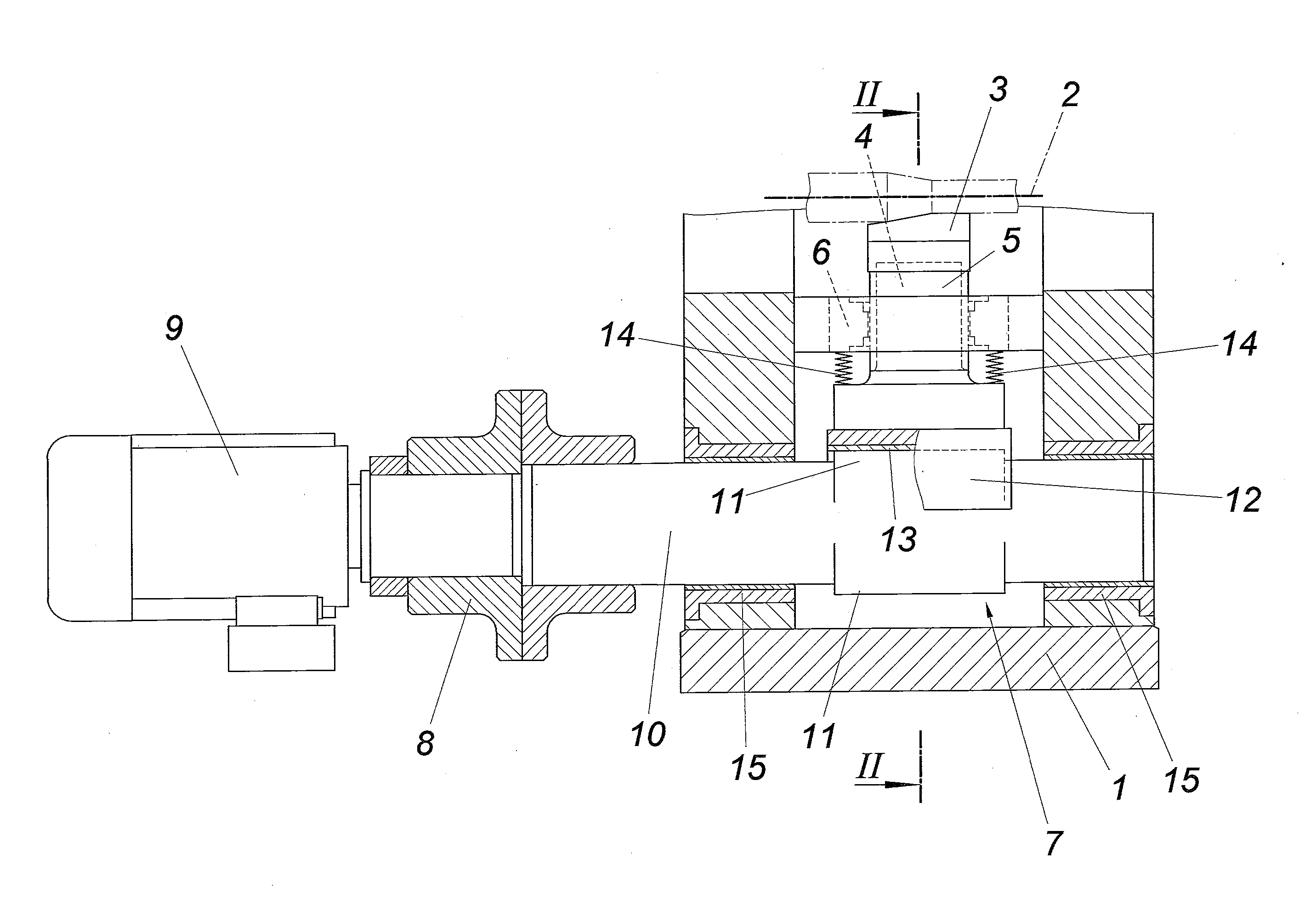
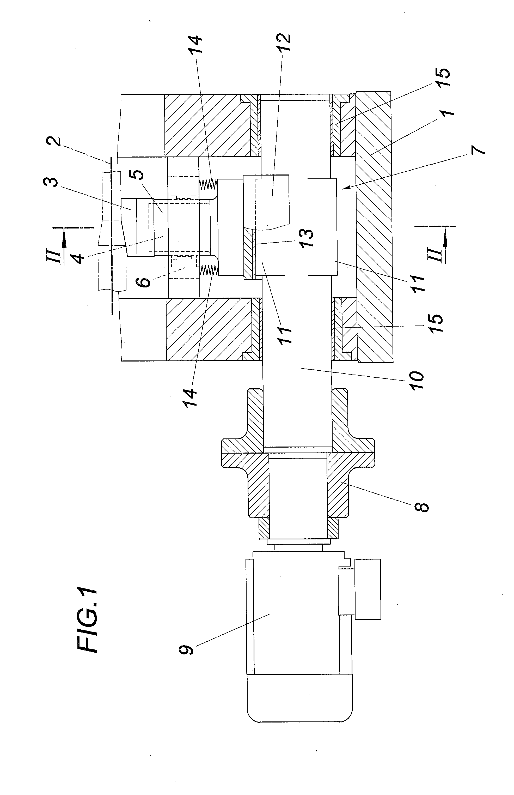
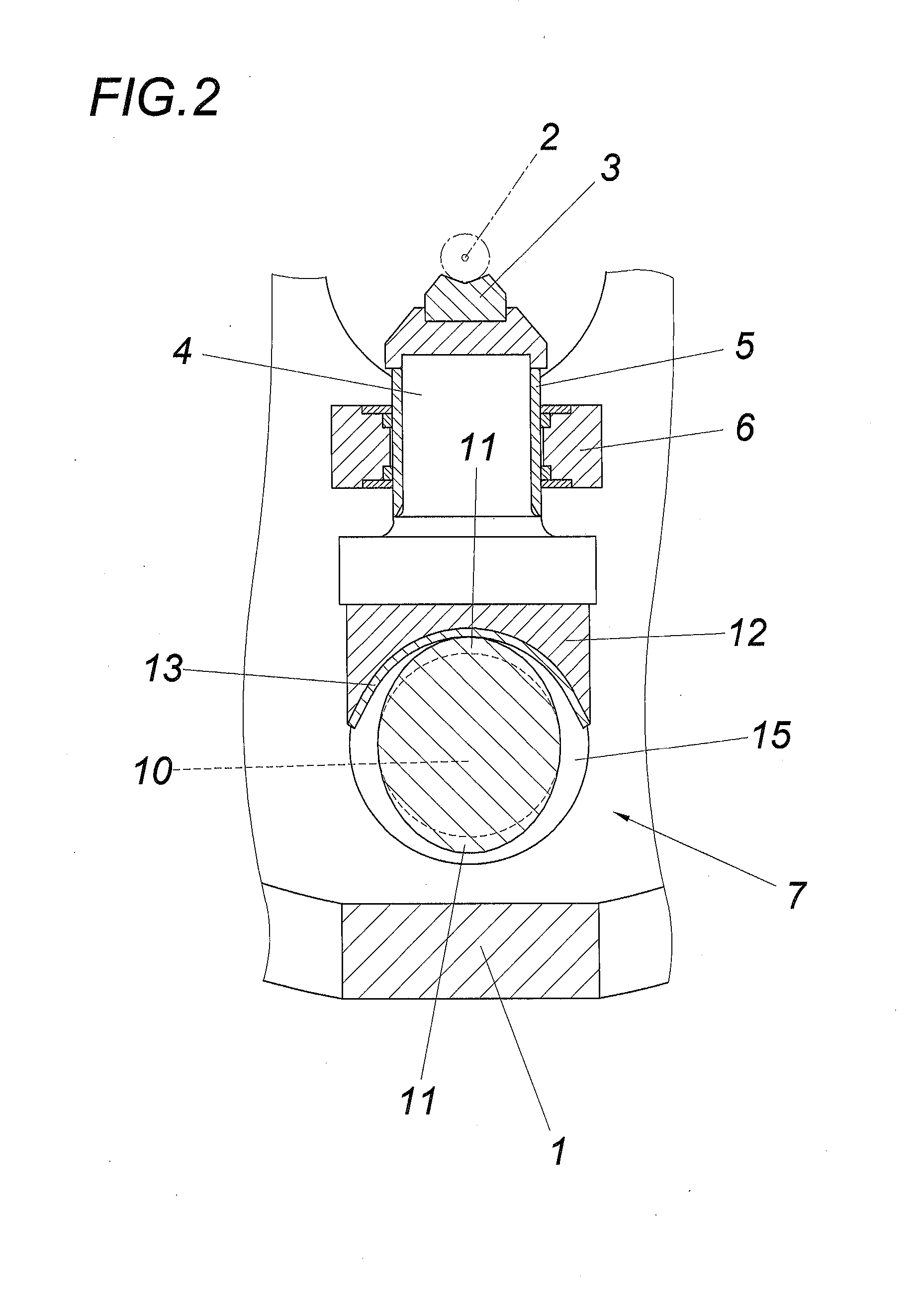
[0016]The forging apparatus according to FIGS. 1 and 2 comprise a frame 1, e.g. having four forging tools 3 which are distributed around a forging axis 2 and which are exchangeably arranged on rams 4. The rams 4, of which only one is shown, are displaceably mounted in the frame 1 radially to the forging axis 3. For this purpose, the frame 1 forms a guide bearing 6 for each ram 4 provided with a sliding sleeve 5.

[0017]The rams 4 are connected to lifting drives 7, which comprise a shaft 10 which is connected via a coupling 8 to a drive motor and which comprise two drive cams 11 which are angularly offset against each other by 180° and are centrally symmetric with respect to the shaft axis. For the purpose of forming these drive cams 11, the shafts 10 are provided in the cam region with an oval cross-section, as is shown especially in FIG. 2. The drive cams 11 cooperate with abutment 12 of the rams 4, which is provided with a cylindrical bearing shell 13 via which the rams 4 can be hel...


PUM

PropertyMeasurementUnit
Angleaaaaaaaaaa

Abstract

The invention relates to a forging apparatus, comprising forging rams (4) that are guided in the direction of stroke and accommodate forging tools (3), and lifting drives (7) which can be driven by a shaft (10) and which are supported in a non-positive manner on an abutment (12) of the forging rams (4) held under pretension in contact on the lifting drives (7). In order to provide simple constructional conditions it is proposed that the shafts (10) of the lifting drives (7) comprise two drive cams (11) which are angularly offset by 180° in relation to each other, are centrally symmetric with respect to the shaft axis, and cooperate with the abutments (12) of the forging rams (4).

Description

FIELD OF THE INVENTION[0001]The invention relates to a forging apparatus, comprising forging rams that are guided in the direction of stroke and accommodate forging tools, and lifting drives which can be driven by a shaft and which are supported in a non-positive manner on an abutment of the forging rams held under pretension in contact on the lifting drives.DESCRIPTION OF THE PRIOR ART[0002]In order to utilise the advantages of eccentric drives for the drive of the forging rams of forging apparatuses without having to use a connecting rod for the transmission of forces between the eccentric and the forging ram accommodating a forging tool, it is known (EP 0 667 197 A1) to mount a sliding block on the eccentric, which sliding block rests in a non-positive manner on an abutment of the forging ram formed in the shape of a sliding plate, so that high pressure forces can be transmitted to the forging ram via the sliding block. As a result of the non-positive support of the sliding block...

Claims


Application Information

Patent Timeline
IPC IPC(8): B21D22/02
CPCB21D22/02B21J9/18B21J7/14B21J7/20B21J7/18
Inventor SEEBER, ALFRED
Owner GFM GMBH
Why Eureka
Try Eureka