Carbon fiber composite material ball head node and connecting method thereof

A technology of carbon fiber materials and composite materials, applied in the direction of pivotal connections, shafts and bearings, mechanical equipment, etc., can solve the problems of reducing the specific strength and specific stiffness of the structure, the difficulty of forming thread processing, increasing the weight of the overall structure, etc., to achieve thermal expansion Good consistency of coefficients, good consistency of structural strength, and the effect of reducing types and quantities

Pending Publication Date: 2021-06-11
NANJING INST OF ASTRONOMICAL OPTICS & TECH NAT ASTRONOMICAL OBSE
View PDF0 Cites 0 Cited by
  • Summary
  • Abstract
  • Description
  • Claims
  • Application Information

AI Technical Summary

Problems solved by technology

The embedded metal method is to embed metal parts when the carbon fiber composite material nodes and pipe fittings are formed, and set up connection structures such as threads and flanges on the metal parts. Through these connection structures, the carbon fiber composite material nodes and pipe fittings are connected, and the embedded metal parts Due to the need to pre-embed the metal structure, on the one hand, it will increase the weight of the overall structure and reduce the specific strength and specific stiffness of the structure;
The so-called forming thread connection method refers to the method of directly manufacturing threads and relying on the thread to connect when the carbon fiber composite material node is formed. The processing quality of the formed thread depends on the thread structure and forming process. After the formed thread is processed, the axis angle cannot be adjusted. Different joints may require different molds to form, and the current forming thread processing is relatively difficult, and the thread quality is not high, which affects the yield of carbon fiber composite joint structures

Method used


Image

  • Carbon fiber composite material ball head node and connecting method thereof
  • Carbon fiber composite material ball head node and connecting method thereof

Examples


Embodiment Construction

[0030] The present invention will be described in further detail below in conjunction with the accompanying drawings.

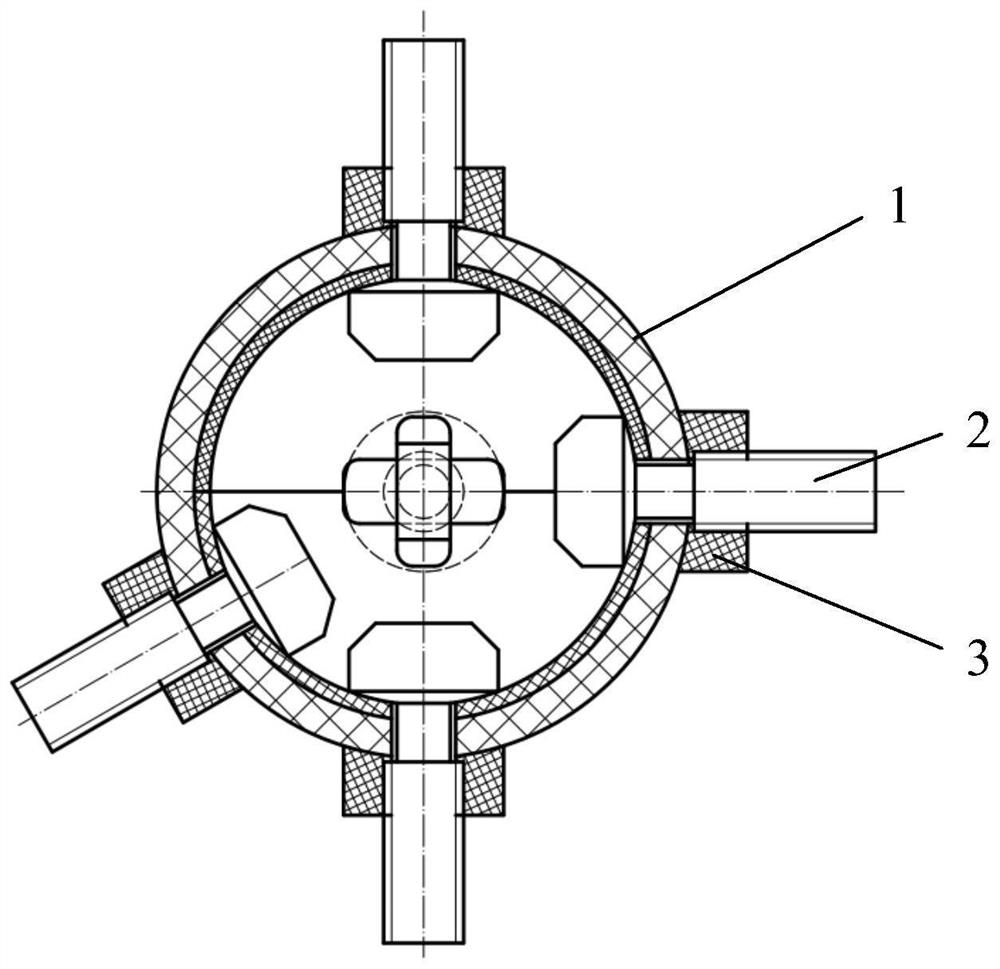
[0031] This embodiment provides a figure 1 The carbon fiber composite ball joint shown. The carbon fiber composite ball joint includes a ball joint 1 , a T-shaped screw 2 and a concave nut 3 . The ball head 1, the T-shaped screw 2 and the concave nut 3 are all made of carbon fiber material. The ball head 1 is a hollow sphere structure. There are several elongated holes on the ball head 1. The length of the elongated holes is greater than the width. It is best to round the corners. The number of elongated holes is the same as the number of pipes pre-connected by the ball head. In this embodiment, the number of elongated holes is specifically 5, and the position of the elongated holes is determined by the position and angle of the pipes pre-connected by the ball head. Decide. A T-shaped screw rod 2 and a concave nut 3 are installed in an elongated hole for c...


PUM


Abstract

The invention discloses a carbon fiber composite material ball head node and a connecting method thereof. The ball head node comprises a ball head, T-shaped screws and concave nuts; the ball head, the T-shaped screws and the concave nuts are all made of carbon fiber materials, the ball head is of a hollow ball structure, a plurality of long holes are formed in the ball head, the length of each long hole is larger than the width of each long hole, and each long hole is provided with one T-shaped screw and one concave nut and is connected with one pipe fitting. The connecting method comprises the steps that the ball head is slightly clamped by the T-shaped screws and the concave nuts, then the direction of the axis of each T-shaped screw is adjusted to a design value, finally, each concave nut is tightened, and the thread meshing positions and the contact positions of the concave nuts and the ball head are coated with epoxy resin glue and cured. Other structures are not needed for supporting and assisting solidification of the whole truss, the construction condition can be greatly simplified, the construction period is shortened, and the ball head node is of great significance in site construction of a large truss structure.

Description

technical field [0001] The invention relates to the technical field of composite materials, in particular to a structure, a forming method and a connection method of a carbon fiber composite material ball joint. Background technique [0002] Compared with traditional steel, carbon fiber composites have the advantages of higher specific stiffness and specific strength. Applying carbon fiber composite materials to large-scale astronomical telescopes can help reduce the weight and drive power consumption of the telescope, and increase the natural frequency and pointing speed of the telescope. In the large truss structure of a large astronomical telescope, the connection technology of carbon fiber composite material nodes and pipes is the key technology of truss forming. The nodes of the large truss of a large astronomical telescope have the following characteristics: 1) the number of pipes connected by a single node is greater than 3, and the typical number of pipes is 8 to 10...

Claims


Application Information

Patent Timeline
Patent Type & Authority Applications(China)
IPC IPC(8): F16C11/06
CPCF16C11/06F16C11/0604
Inventor 乐中宇陈萌顾伯忠姜翔张志永叶宇徐进
Owner NANJING INST OF ASTRONOMICAL OPTICS & TECH NAT ASTRONOMICAL OBSE
Why Eureka
Try Eureka