Supercharge Your Innovation With Domain-Expert AI Agents!

Tank mounting structure and vehicle

a technology for mounting structures and tanks, applied in the direction of vehicle sub-unit features, vehicle discharging methods, battery/cell propulsion, etc., can solve problems such as damage to tanks, and achieve the effect of preventing expansion of gaps

Active Publication Date: 2019-05-30
TOYOTA JIDOSHA KK
View PDF0 Cites 1 Cited by
  • Summary
  • Abstract
  • Description
  • Claims
  • Application Information

AI Technical Summary

Benefits of technology

The patent describes a tank mounting structure that prevents damage to the tank caused by external force. The structure includes a frame, band, and tank protector. The tank protector moves along with the tank as it expands or contracts, reducing the gap between the tank and the protector. The tank protector is designed to protect the tank from damage, while also reducing the weight of the tank. The technical effect of this structure is to provide a safer and lighter tank mounting system.

Problems solved by technology

As a result, the tank can be damaged.

Method used


Image

  • Tank mounting structure and vehicle
  • Tank mounting structure and vehicle
  • Tank mounting structure and vehicle

Examples


Embodiment Construction

A. Embodiments

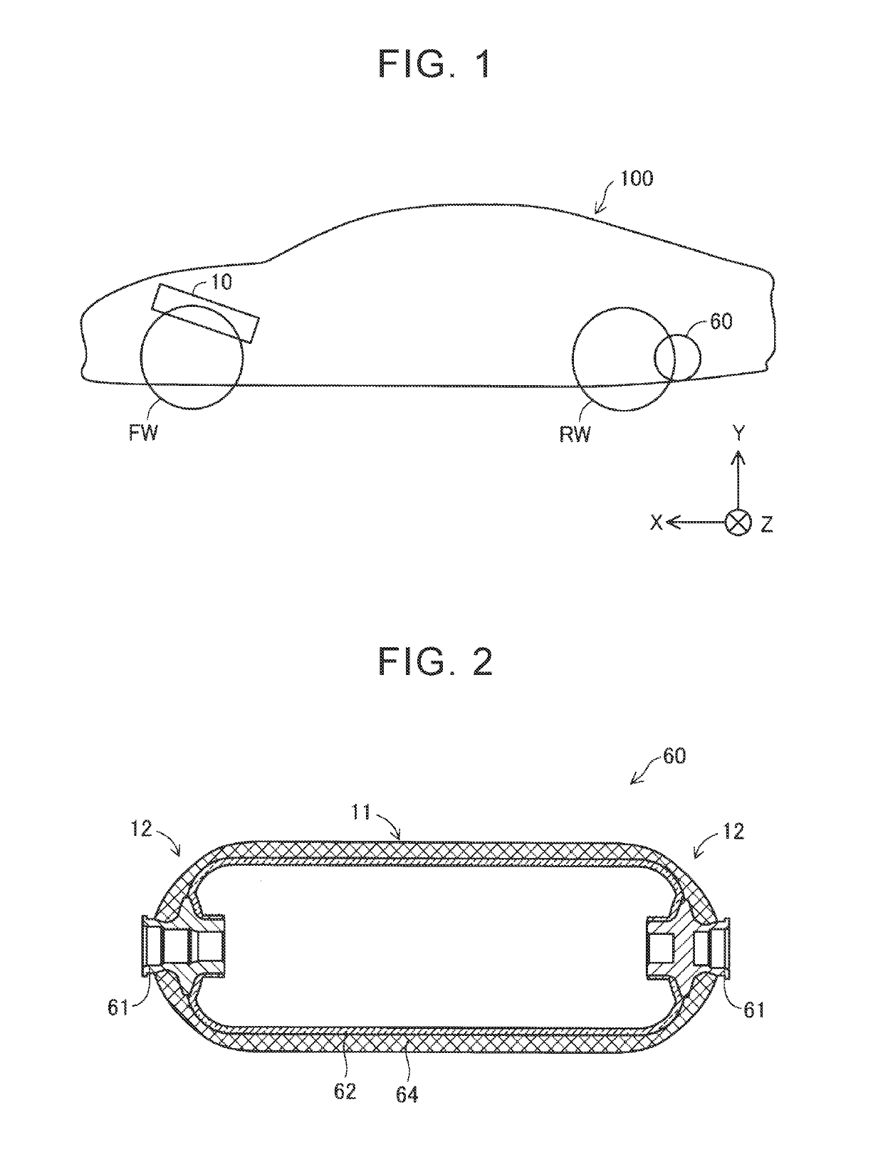
[0016]FIG. 1 is a view of a vehicle 100 having a mounting structure of a tank 60 as an embodiment of the disclosure. In the embodiment, a fuel cell vehicle is used as the vehicle 100. Description regarding directions in the vehicle 100 (“right”, “left”, “front”, “rear”, “upper”, and “lower”) indicates directions based on a driver who is in the vehicle 100, respectively. In FIG. 1, an X axis forward direction indicates a vehicle front direction, a Y axis forward direction indicates an upper side of the gravity direction, and a Z axis forward direction indicates a vehicle right direction. This means that the X axis direction indicates a front-rear direction of the vehicle, the Y axis direction indicates the gravity direction, and the Z axis direction indicates a width direction of the vehicle. The X, Y, and Z axes are the same in the drawings after FIG. 1.

[0017]The vehicle 100 includes a fuel cell stack 10 and the tank 60. The fuel cell stack 10 is made by laminating pow...


PUM


Abstract

A tank mounting structure includes a frame, a band, and a tank protector. The frame is configured to fix the tank. The band is configured to fix the tank in a state where the band sandwiches the tank with the frame and the band deforms in accordance with expansion or contraction of the tank. The tank protector is configured to be fixed to an inner side of the band or an outer side of the band.

Description

INCORPORATION BY REFERENCE[0001]The disclosure of Japanese Patent Application No. 2017-228838 filed on Nov. 29, 2017 including the specification, drawings and abstract is incorporated herein by reference in its entirety.BACKGROUND1. Technical Field[0002]The disclosure relates to a tank mounting structure and a vehicle.2. Description of Related Art[0003]In Japanese Unexamined Patent Application Publication No. 2005-119595 (JP 2005-119595 A), a structure is disclosed in which a protector that covers a rear side of a tank body is provided in a rear axle of a vehicle in order to mitigate an impact on the tank that stores gas used for a fuel cell.SUMMARY[0004]Normally, a tank expands and contracts depending on an amount gas stored. Therefore, in the configuration described in JP 2005-119595 A, when the tank contracts, a gap between the tank and the protector can expand. Also, when the protector receives force from outside in a state where a foreign object such as a large stone is trapped...

Claims


Application Information

Patent Timeline
IPC IPC(8): B60K15/07F17C13/08
CPCB60K15/07F17C13/084F17C2201/0109F17C2201/035F17C2201/05B60L50/70B60K2015/03315B60K2015/0675B60K15/03006B60K15/03177B60K2015/03046B60Y2306/01F17C2221/012F17C2205/0305F17C2203/0619F17C2203/0604F17C2201/056F17C2223/0123F17C2223/036F17C2205/0192F17C2270/0178Y02E60/32Y02T90/40Y02E60/50B60K2015/03453B60K2015/0638
Inventor FUJII, MANABU
Owner TOYOTA JIDOSHA KK
Features
  • R&D
  • Intellectual Property
  • Life Sciences
  • Materials
  • Tech Scout
  • Unparalleled Data Quality
  • Higher Quality Content
  • 60% Fewer Hallucinations
Learn More