Vacuum monitor

a vacuum monitor and monitor technology, applied in the field of vacuum monitors, can solve the problem of not being able to achieve film formation using intended components, and achieve the effect of reducing frequency, shortening the lifespan of vacuum monitors, and increasing miniaturization in semiconductor manufacturing processing

Inactive Publication Date: 2019-05-30
HORIBA STEC CO LTD
View PDF0 Cites 3 Cited by
  • Summary
  • Abstract
  • Description
  • Claims
  • Application Information

AI Technical Summary

Benefits of technology

[0019]In this way, according to the vacuum monitor according to the present invention, because the set temperature of the heater that adjusts the temperature of the sensing mechanism is adjustable, in cases in which various different types of gas are introduced into a measurement space, it is possible to set a temperature that corresponds to the types of gas, and prevent components in the gases from being dep...

Problems solved by technology

Moreover, if the temperature of the material gases is raised in order to prevent condensation, then there a...

Method used


Image

  • Vacuum monitor
  • Vacuum monitor
  • Vacuum monitor

Examples


Embodiment Construction

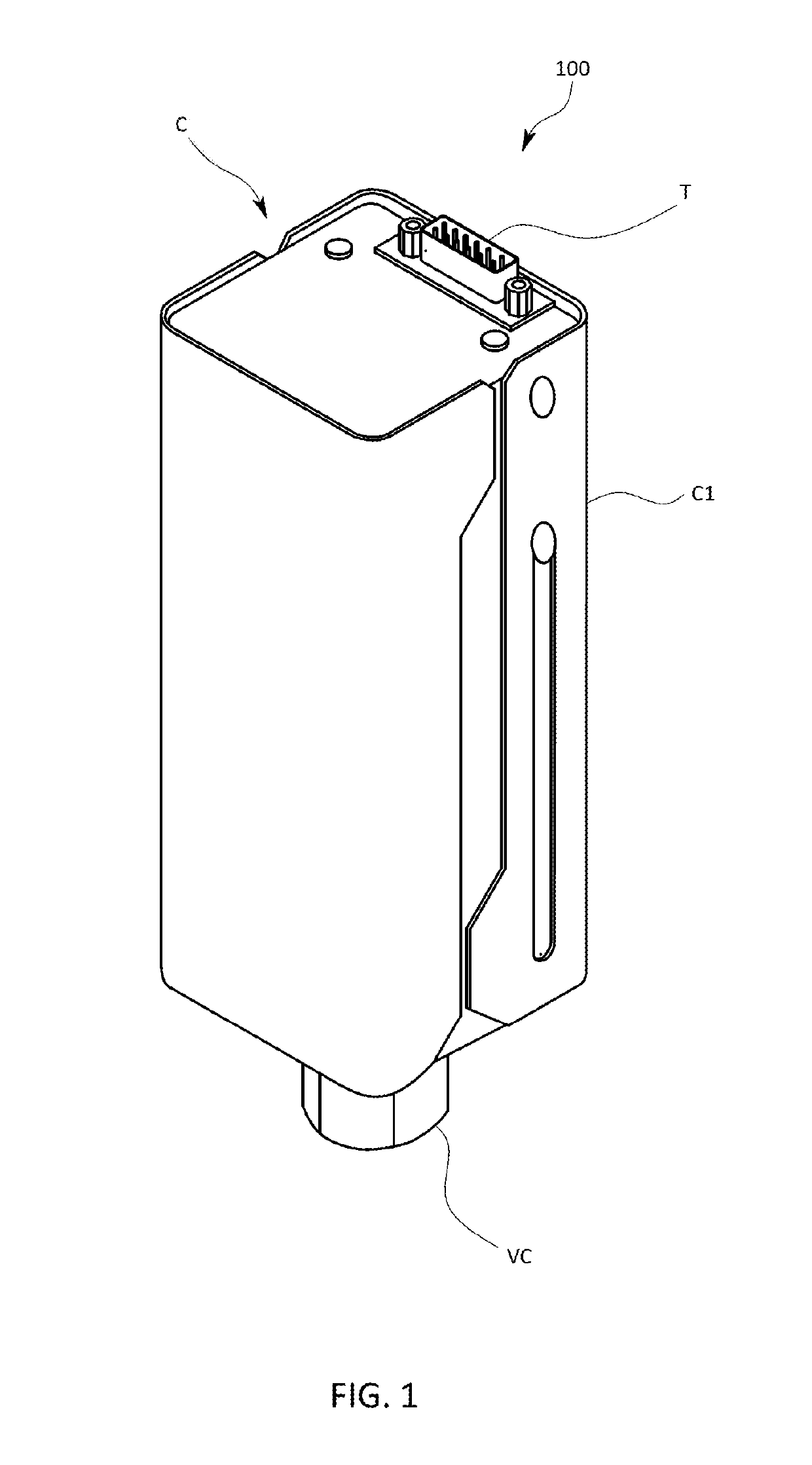
[0027]A vacuum monitor 100 according to an embodiment of the present invention will now be described with reference to FIG. 1 through FIG. 7.

[0028]The vacuum monitor 100 of the present embodiment is used, for example, in order to monitor a degree of vacuum inside a vacuum chamber which is a measurement space where film formation and the like are performed in a semiconductor manufacturing process. The vacuum monitor 100 is provided on an outer side of a partitioning wall of the vacuum chamber, and is connected so as to be able to communicate with an interior portion of the vacuum chamber.

[0029]As is shown in FIG. 1, the pressure gauge 100 has a substantially parallelepiped-shaped configuration and has a vacuum coupling VC provided at a distal end portion thereof, and an output terminal T that is used to output measured pressure values to the outside provided at a base end portion thereof.

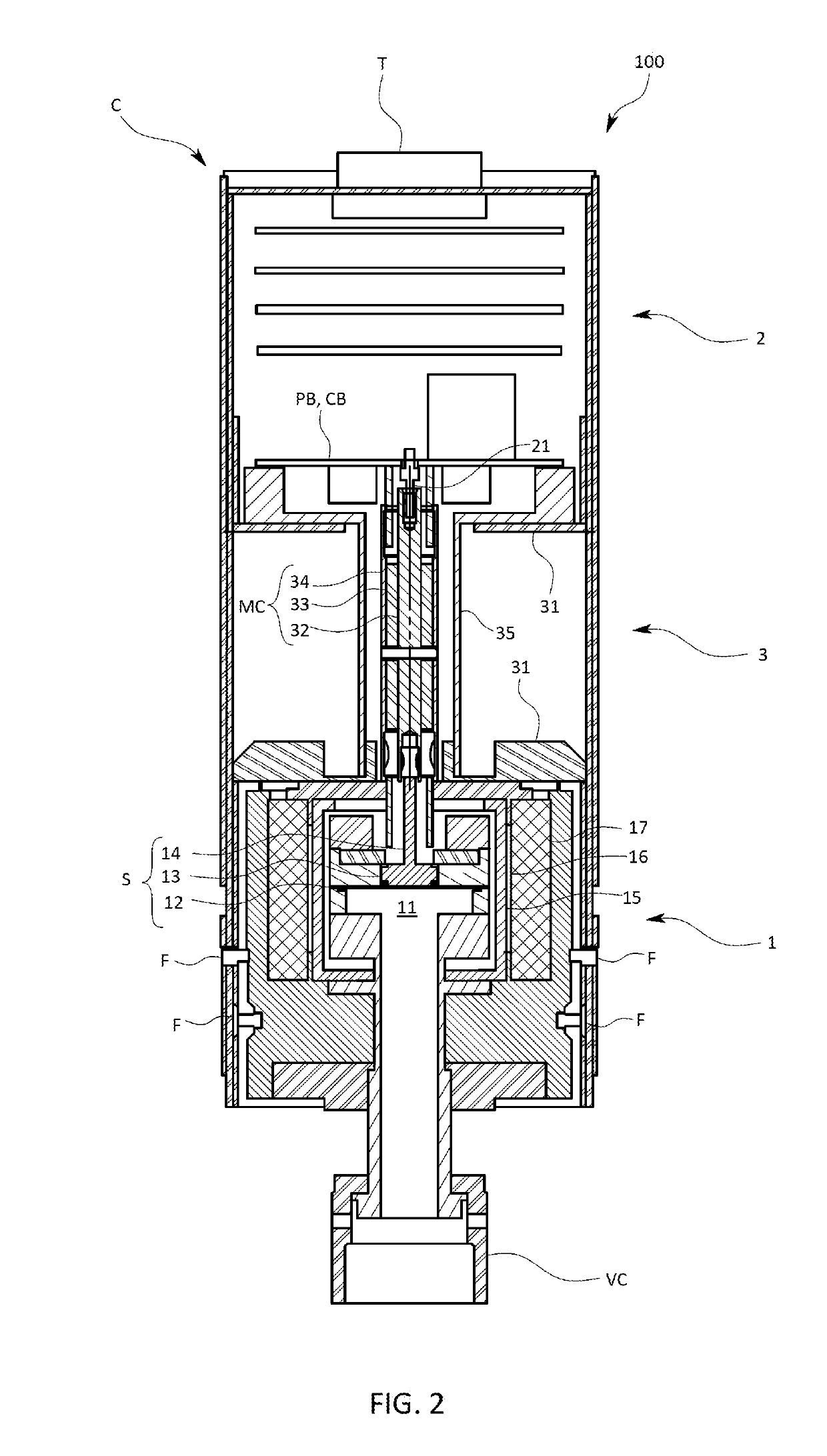
[0030]As is shown in cross-sectional view in FIG. 2, in the vacuum monitor 100, three modules are...


PUM


Abstract

In order to provide a vacuum monitor that, even if a sensing mechanism is exposed to an atmosphere into which various types of material gases are introduced, enables the deposition of matter on the sensing mechanism to be prevented, and enables the lifespan of the sensing mechanism to be extended, there are provided a sensing mechanism that is in contact with an atmosphere inside a measurement space, and outputs an output signal that corresponds to a pressure inside this measurement space, and a heater that adjusts a temperature of the sensing mechanism, wherein a set temperature of the heater is adjustable.

Description

TECHNICAL FIELD[0001]The present invention relates to a vacuum monitor.TECHNICAL BACKGROUND[0002]For example, in a semiconductor manufacturing process, a vacuum monitor that is used to monitor a degree of vacuum is provided inside a vacuum chamber where film formation is performed. As is shown in Patent document 1, a vacuum monitor is provided with a sensing mechanism that is exposed to the atmosphere inside a vacuum chamber, and with a pressure calculation circuit into which is input an output signal which is output from the sensing mechanism in accordance with the pressure, and that converts this output signal into a pressure signal which shows the pressure.[0003]In recent years, in conjunction with the increasing miniaturization required in semiconductor manufacturing processing, an increasing variety of diverse material gases are being introduced into the vacuum chamber, and among these new material gases are those whose condensation temperature is far higher than that of conven...

Claims


Application Information

Patent Timeline
IPC IPC(8): G01L19/14G01L21/12G01L9/12G01L9/00
CPCG01L19/14G01L21/12G01L9/125G01L9/0072G01L21/00G01L19/06G01L19/142G01L27/002G01L21/30G01L21/22H01L21/67248H01L21/67098H01L21/67276H01L21/67207
Inventor KISHIDA, SOTAROYAMASHITA, KEISUKENAKAI, JUNYA
Owner HORIBA STEC CO LTD
Why Eureka
Try Eureka