Method for modifying and controlling magnetic field and apparatus for the same

a magnetic field and strength technology, applied in the direction of nmr measurement, instruments, therapy, etc., can solve the problems of reducing the efficiency and affecting the effect of the magnetic field strength, etc., to achieve the effect of reducing the use of equipment, convenient use and efficient implementation

Active Publication Date: 2019-05-30
ELECTRONICS & TELECOMM RES INST
View PDF2 Cites 2 Cited by
  • Summary
  • Abstract
  • Description
  • Claims
  • Application Information

AI Technical Summary

Benefits of technology

[0014]Another object of the present invention is to minimize the use of equipment that is required in order to modify the strength of a magnetic field.
[0015]A further object of the present invention is to provide a method for modifying a magnetic field, which is more easily used and is more efficiently implemented from the standpoint of expense than a method using multiple coils.

Problems solved by technology

However, this configuration is problematic in that many coils must be used and in that a power supply, a controller required for current control, etc. are additionally required in order to supply electricity to the many coils.
Further, once a coil having such a structure is manufactured, it is realistically almost impossible to modify the coil structure, and thus an operational problem arises in that expensive coils must be discarded or manufactured again.
Furthermore, when a magnetic field having a specific strength is intended to be formed in a specific portion of a sample, there is inconvenience in that at least four voltages / currents must be adjusted in a 2D space and at least six voltages / currents must be adjusted in a 3D space, and the adjusted currents / voltages must be actually measured and then used.
In order to overcome this inconvenience, a system function for a coil must be generated, and a lot of time is taken to reach a desired solution.
Also, there is technical inconvenience in that, in order to obtain a 3D resonance signal related to the specific portion, the entire portion corresponding to the periphery of the specific portion must be imaged, after which information about the specific portion must be acquired based on imaged results.

Method used


Image

  • Method for modifying and controlling magnetic field and apparatus for the same
  • Method for modifying and controlling magnetic field and apparatus for the same
  • Method for modifying and controlling magnetic field and apparatus for the same

Examples


Embodiment Construction

[0066]The present invention will be described in detail below with reference to the accompanying drawings. Repeated descriptions and descriptions of known functions and configurations which have been deemed to make the gist of the present invention unnecessarily obscure will be omitted below. The embodiments of the present invention are intended to fully describe the present invention to a person having ordinary knowledge in the art to which the present invention pertains. Accordingly, the shapes, sizes, etc. of components in the drawings may be exaggerated to make the description clearer.

[0067]Hereinafter, preferred embodiments of the present invention will be described in detail with reference to the attached drawings.

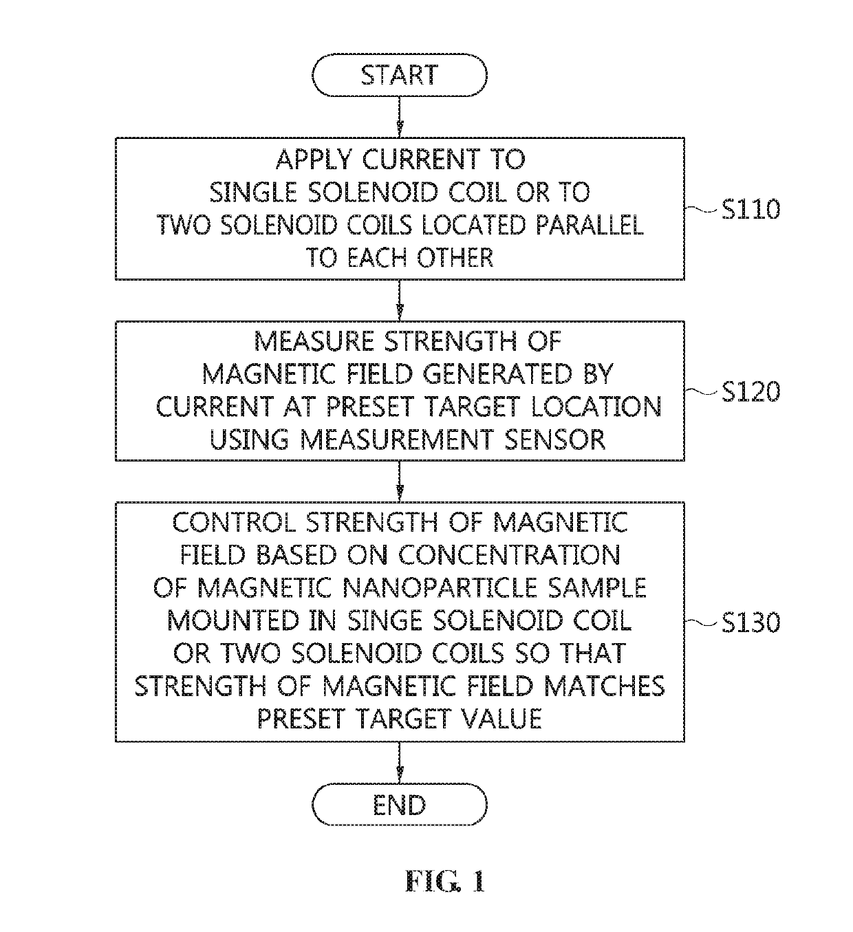
[0068]FIG. 1 is an operation flowchart illustrating a method for modifying a magnetic field according to an embodiment of the present invention.

[0069]Referring to FIG. 1, in the magnetic field modification method according to the embodiment of the present invention, ...


PUM


Abstract

Disclosed herein are a method for modifying a magnetic field using magnetic nanoparticles and an apparatus therefor. The method for modifying a magnetic field includes applying current to a single solenoid coil or to two parallel solenoid coils, measuring a strength of a magnetic field generated by the current at a preset target location using a measurement sensor, and controlling the strength of the magnetic field based on a concentration of a magnetic nanoparticle sample mounted in the single solenoid coil or the two solenoid coils so that the strength of the magnetic field matches a preset target value.

Description

CROSS REFERENCE TO RELATED APPLICATIONS[0001]This application claims the benefit of Korean Patent Application Nos. 10-2017-0162955, filed Nov. 30, 2017 and 10-2017-0162961, filed Nov. 30, 2017, which are hereby incorporated by reference in their entirety into this application.BACKGROUND OF THE INVENTION1. Technical Field[0002]The present invention relates generally to technology for changing or controlling the strength of a magnetic field, and more particularly, to technology that can control the strength of a magnetic field using only magnetic nanoparticles without using a multi-coil array, and can also control the strength of a magnetic field so that the magnetic field is usable in fields such as electromagnetics, electric wave engineering, and the development of medical monitoring equipment by adjusting individual currents to be applied to multiple drive coils.2. Description of the Related Art[0003]One of the most essential parts in equipment for acquiring signals or images using...

Claims


Application Information

Patent Timeline
Patent Type & Authority Applications(United States)
IPC IPC(8): G01R33/36G01R33/381G01R33/48
CPCG01R33/36G01R33/381G01R33/48G01N27/72A61N2/00H05G1/60G01R33/12
Inventor HONG, HYO-BONGJEONG, JAE-CHANCHOI, SEUNG-MINKIM, CHANG-BEOM
Owner ELECTRONICS & TELECOMM RES INST
Why Eureka
Try Eureka