

Display device
a display panel and display technology, applied in the direction of transducer diaphragms, electromechanical transducers, instruments, etc., can solve the problems of difficult piezoelectric speakers to obtain sufficient sound pressure in a low frequency range of 1 khz or less, and heat generation in the display panel
- Summary
- Abstract
- Description
- Claims
- Application Information
AI Technical Summary
Benefits of technology
Problems solved by technology
Method used
Image

Examples
first embodiment
[0093]As shown in FIG. 6A, a display device according to the present invention includes a double-sided adhesive layer 250 interposed between and surface-attached to the rear surface of a display panel 100 and a first surface of a piezoelectric element 200. The display device may further include an insulator film 260 arranged on the side of a second surface of the piezoelectric element 200 so as to be spaced apart from the bottom cover 300. The insulator film 260 may be an inorganic film of an oxide film, a nitride film, or an oxynitride film, or an imide or amine-based thin organic film. The insulator film 260 serves to prevent contact between the metallic bottom cover 300 and the piezoelectric element 200 and to prevent influence on driving of the piezoelectric element 200 through electrical insulation between the bottom cover 300 and the piezoelectric element 200. Here, the first surface and the second surface of each piezoelectric element 200 are electrodes, and an electrical sig...
second embodiment
[0094]The display device according to the present invention shown in FIG. 6B further includes a damping member 350 disposed between the second surface of the piezoelectric element 200 and the bottom cover 300. The damping member 350 replaces the insulator film 260 described above.
[0095]Here, the damping member 350 is formed of a high-elasticity resin. The damping member 350 may be required to attenuate vibration transmitted to the bottom cover 300 because the vibration produced when an electrical signal is applied to the piezoelectric element 200 is transmitted to both the display panel 100, which corresponds to the front face of the piezoelectric element 200, and the bottom cover 300, which corresponds to the rear surface of the piezoelectric element 200, but only the front surface of the display panel 100 is needed when actually listening to sound. The damping member 350 is a kind of buffer member. If the gap between the bottom cover 300 and the piezoelectric element 200 is suffic...
fifth embodiment
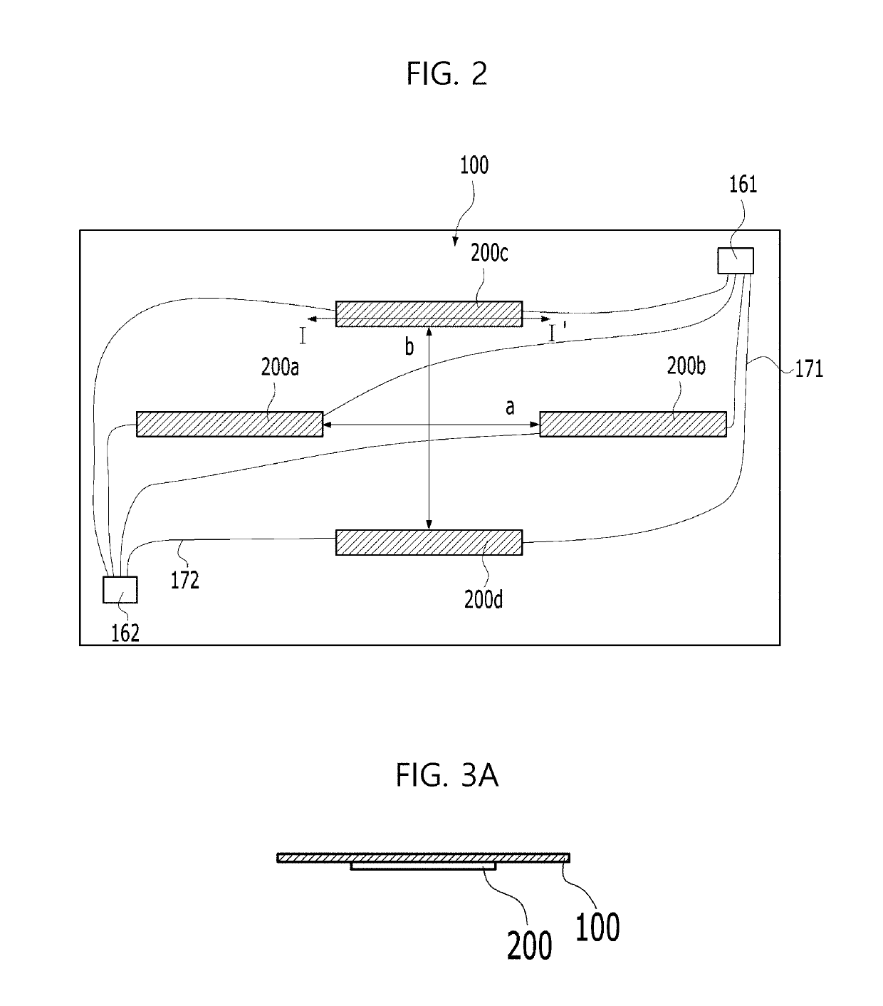
[0108]A display device corresponding to FIG. 12A includes first to fourth piezoelectric elements 400a, 400b, 400c, and 400d arranged at the corners of an imaginary rectangle on the rear surface of the display panel 100.
[0109]In this case, without increasing the number of piezoelectric elements from the number of piezoelectric elements of the display device of FIG. 1, a first pair of piezoelectric elements 400a and 400b spaced apart from each other by a first distance a, a second pair of piezoelectric elements 400c and 400d spaced apart from each other by the first distance a, a third pair of piezoelectric elements 400a and 400c spaced apart from each other by a second distance b crossing the first distance a, and a fourth pair of piezoelectric elements 400b and 400d spaced apart from each other by the second distance b are defined, and the piezoelectric elements of each pair may reinforce the sound pressure level of a specific frequency, thereby enhancing the sound pressure level i...
PUM
 Abstract
Description
Claims
Application Information