
Light emitting diode for display and display apparatus having the same

a technology of light-emitting diodes and display apparatus, which is applied in the direction of basic electric elements, electrical apparatus, and semiconductor devices. it can solve the problems of reducing the luminous area, deteriorating brightness, and difficulty in mounting micro-leds on display panels, so as to increase the luminous area of each subpixel without increasing the pixel area

Pending Publication Date: 2019-05-30
SEOUL VIOSYS CO LTD
View PDF13 Cites 17 Cited by
  • Summary
  • Abstract
  • Description
  • Claims
  • Application Information

AI Technical Summary

Benefits of technology

The present disclosure provides a light emitting diode for a display that can increase the luminous area of each subpixel without increasing the pixel area. Additionally, this LED allows for the simultaneous manufacture of multiple pixels and does not require individual mounting on the display panel. This results in a more efficient and effective display apparatus.

Problems solved by technology

However, the micro-LED has a very small size of 200 μm or less, or a size of 100 μm or less, thereby causing various problems.
In particular, it is difficult to mount the micro-LEDs on a display panel due to difficulty in handling of the micro-LEDs and to replace defective micro-LEDs among the micro-LEDs on the display panel with new micro-LEDs.
Thus, the area of each subpixel must be reduced in order to arrange the subpixels in a limited area, thereby causing deterioration in brightness due to reduction in luminous area.
However, increase in the area of the LED causes increase in an area occupied by a subpixel.
Moreover, although brightness difference can be reduced through regulation of current density applied to each LED, reduction in brightness difference depending upon visibility through regulation of current density makes operation of a display complex and difficult.

Method used


Image

  • Light emitting diode for display and display apparatus having the same
  • Light emitting diode for display and display apparatus having the same
  • Light emitting diode for display and display apparatus having the same

Examples


Embodiment Construction

[0289]Hereinafter, exemplary embodiments of the present disclosure will be described in detail with reference to the accompanying drawings. The following embodiments are provided by way of example so as to fully convey the spirit of the present disclosure to those skilled in the art to which the present disclosure pertains. Accordingly, the present disclosure is not limited to the embodiments disclosed herein and can also be implemented in different forms. In the drawings, widths, lengths, thicknesses, and the like of elements can be exaggerated for clarity and descriptive purposes. When an element or layer is referred to as being “disposed above” or “disposed on” another element or layer, it can be directly “disposed above” or “disposed on” the other element or layer or intervening elements or layers can be present. Throughout the specification, like reference numerals denote like elements having the same or similar functions.

[0290]Hereinafter, exemplary embodiments of the present ...


PUM


Abstract

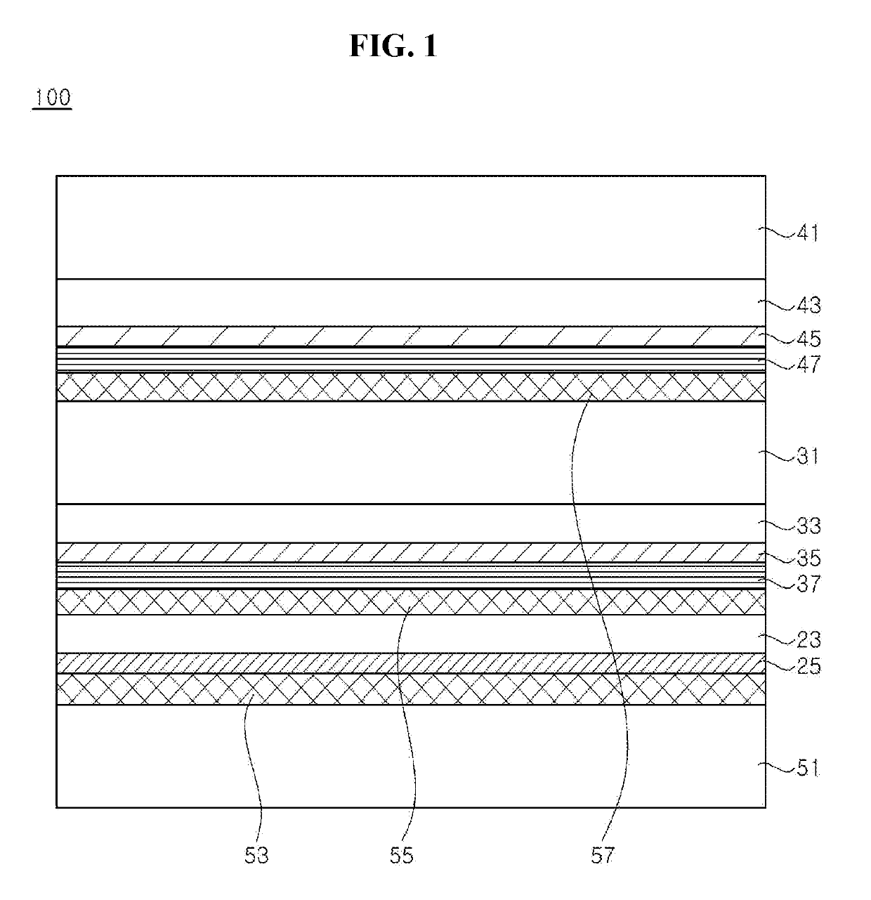
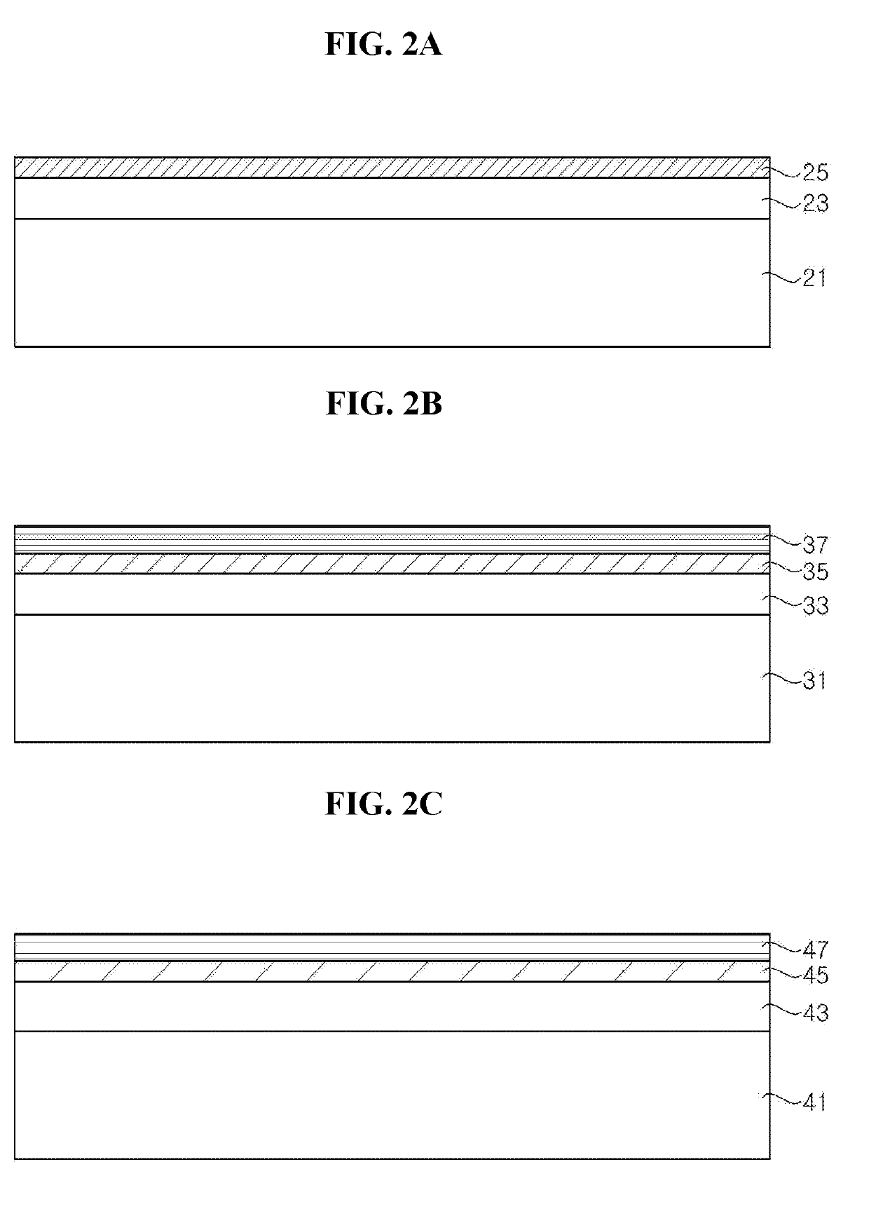
A light emitting diode stack for a display includes a support substrate, a first LED stack, a second LED stack, and a third LED stack, a conductive growth substrate coupled to the second LED stack or the third LED stack, a first color filter interposed between the first and second LED stacks and transmitting light generated from the first LED stack while reflecting light generated from the second LED stack, and a second color filter interposed between the second and third LED stacks and transmitting light generated from the first and second LED stacks while reflecting light generated from the third LED stack, in which light generated from the first LED stack is emitted outside through the second LED stack, the third LED stack, and the conductive growth substrate, and light generated from the second LED stack is emitted outside through the third LED stack and the conductive growth substrate.

Description

CROSS-REFERENCE TO RELATED APPLICATIONS[0001]This application claims priority from and the benefit of U.S. Provisional Patent Application No. 62 / 590,830, filed on Nov. 27, 2017, U.S. Provisional Patent Application No. 62 / 595,415, filed on Dec. 6, 2017, U.S. Provisional Application No. 62 / 597,614, filed on Dec. 12, 2017, U.S. Provisional Patent Application No. 62 / 598,223, filed on Dec. 13, 2017, U.S. Provisional Patent Application No. 62 / 621,492, filed on Jan. 24, 2018, U. S. Provisional Patent Application No. 62 / 624,639, filed on Jan. 31, 2018, and U.S. Provisional Patent Application No. 62 / 624,667, filed on Jan. 31, 2018, each of which are incorporated by reference for all purposes as if fully set forth herein.BACKGROUNDField[0002]Exemplary embodiments of the present disclosure relate to a light emitting diode for a next generation display and a display apparatus having the same.Discussion of the Background[0003]As an inorganic light source, light emitting diodes have been used in ...

Claims


Application Information

Patent Timeline
Patent Type & Authority Applications(United States)
IPC IPC(8): H01L25/13H01L33/38H01L33/40H01L33/50H01L27/15H01L33/62
CPCH01L25/13H01L33/38H01L33/405H01L33/50H01L27/156H01L33/62H01L25/0753H01L25/0756H01L33/0093H01L33/0008H01L33/58
Inventor CHAE, JONG HYEONKIM, CHANG YEONLEE, HO JOONJANG, SEONG GYULEE, CHUNG HOONCHO, DAE SUNG
Owner SEOUL VIOSYS CO LTD
Learn More