Projection optical system and projection type image display device

Active Publication Date: 2019-05-30
SEIKO EPSON CORP
View PDF4 Cites 1 Cited by
  • Summary
  • Abstract
  • Description
  • Claims
  • Application Information

AI Technical Summary

Benefits of technology

[0017]According to the aspect of the invention, it is possible to suppress the number of lens elements while correcting aberration in the projection optical system. In addition, when the number of lens elements of the project

Problems solved by technology

When Conditional Expression (7) exceeds an upper limit, it b

Method used


Image

  • Projection optical system and projection type image display device
  • Projection optical system and projection type image display device
  • Projection optical system and projection type image display device

Examples


example 1

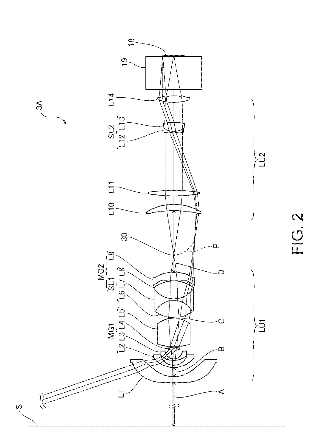
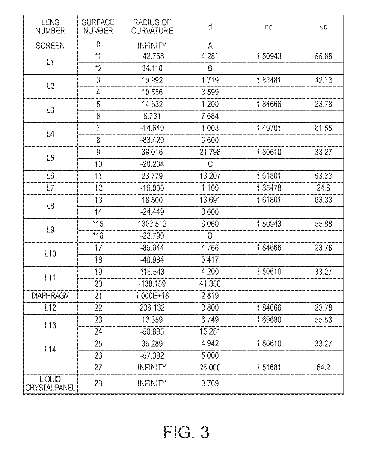
[0044]FIG. 2 is a configuration diagram (light beam diagram) of a projection optical system according to Example 1. FIG. 3 is a diagram illustrating lens data of the projection optical system according to Example 1. FIG. 4 is a diagram illustrating aspherical data of an aspherical lens of the projection optical system according to Example 1. As illustrated in FIG. 2, a projection optical system 3A in the present example includes a first lens unit LU1 that conjugates the screen S which is an enlargement-side image forming surface and an intermediate image 30, and a second lens unit LU2 that conjugates the intermediate image 30 and the liquid crystal panels 18 (18R, 18G, 18B) which are reduction-side image forming surfaces. The projection optical system 3A includes fourteen lens elements.

[0045]The first lens unit LU1 includes nine lens elements. That is, the first lens unit LU1 includes a first lens unit first lens L1, a first lens unit second lens L2, a first lens unit third lens L3,...

example 2

[0078]FIG. 6 is a configuration diagram (light beam diagram) of a projection optical system according to Example 2. FIG. 7 is a diagram illustrating lens data of the projection optical system according to Example 2. FIG. 8 is a diagram illustrating aspherical data of an aspherical lens of the projection optical system according to Example 2. As illustrated in FIG. 6, a projection optical system 3B in the present example includes a first lens unit LU1 that conjugates a screen S which is an enlargement-side image forming surface and an intermediate image 30, and a second lens unit LU2 that conjugates the intermediate image 30 and liquid crystal panels (18R, 18G, 18B) which are reduction-side image forming surfaces. The projection optical system. 3B includes fourteen lens elements.

[0079]The first lens unit LU1 includes ten lens elements. That is, the first lens unit LU1 includes a first lens unit first lens L1, a first lens unit second lens L2, a first lens unit third lens L3, a first ...

example 3

[0112]FIG. 10 is a configuration diagram (light beam diagram) of a projection optical system according to Example 3. FIG. 11 is a diagram illustrating lens data of the projection optical system according to Example 3. FIG. 12 is a diagram illustrating aspherical data of an aspherical lens of the projection optical system according to Example 3. As illustrated in FIG. 10, a projection optical system 3C in the present example includes a first lens unit LU1 that conjugates the screen S which is an enlargement-side image forming surface and an intermediate image 30, and a second lens unit LU2 that conjugates the intermediate image 30 and the liquid crystal panels 18 (18R, 18G, 18B) which are reduction-side image forming surfaces. The projection optical system 3C includes fourteen lens elements.

[0113]The first lens unit LU1 includes nine lens elements. That is, the first lens unit LU1 includes a first lens unit first lens L1, a first lens unit second lens L2, a first lens unit third lens...


PUM


Abstract

A projection optical system includes a first lens unit and a second lens unit interposing an intermediate image therebetween. The first lens unit includes two aspherical lenses (a first lens unit first lens and a first lens unit ninth lens), and a first lens unit cemented lens. The projection optical system satisfies the following Conditional Expressions (1) and (2) when the number of lens elements of the first lens unit and the number of lens elements of the second lens unit are set to be Num1 and Num2, respectively. In addition, refractive indexes and Abbe numbers of three lenses constituting the first lens unit cemented lens satisfy a predetermined conditional expression.
Num2≤7  (1)
1.5≤Num1/Num2≤2.5  (2)

Description

BACKGROUND1. Technical Field[0001]The present invention relates to a projection optical system capable of suppressing the number of lens elements, and a projection type image display device including the projection optical system.2. Related Art[0002]A projection optical system capable of being incorporated into a projection type image display device such as a projector is disclosed in JP-A-2014-29392. When the projection optical system is incorporated into the projection type image display device, the projection optical system disclosed in the document forms an intermediate image of an image of the image display element inside the optical system to form the image on a screen again. That is, the projection optical system includes a first lens unit that conjugates the screen (enlargement-side image forming surface) and the intermediate image and a second lens unit that conjugates the intermediate image and a reduction-side image forming surface (the image of the image display element)...

Claims


Application Information

Patent Timeline
IPC IPC(8): H04N5/74G02B13/06G02B13/16G03B21/14
CPCH04N5/7416G02B13/06G02B13/16G03B21/142G02B27/005G02B13/04G02B27/149
Inventor SHIOKAWA, KOJI
Owner SEIKO EPSON CORP
Why Eureka
Try Eureka