
Method for quantum annealing computation

Active Publication Date: 2020-02-06
NAT INST OF ADVANCED IND SCI & TECH
View PDF0 Cites 0 Cited by
  • Summary
  • Abstract
  • Description
  • Claims
  • Application Information

AI Technical Summary

Benefits of technology

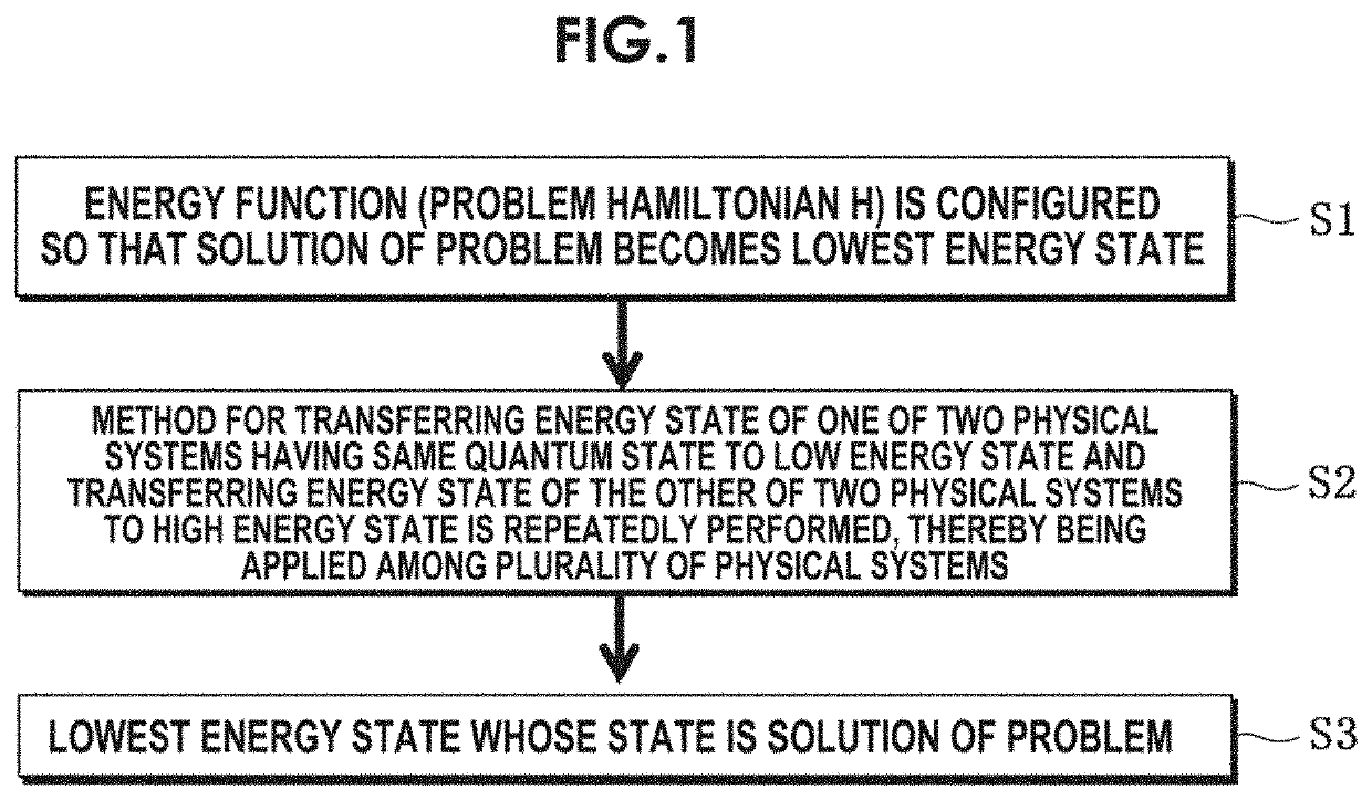
The present invention proposes a new method for guiding a physical state to the lowest energy state, which is different from conventional methods. This new method reduces the number of computation steps and the required number of quantum bits, which reduces computation time and improves efficiency for solving search problems. The number of computation steps can be significantly reduced with the method of the present invention, which helps to suppress an increase in computation time according to the size of the problem.

Problems solved by technology

In particular, when a size of a problem to be solved is big, there exists a problem (bottleneck) that an expectation value of computation time increases exponentially with respect to a size of the problem.

Method used


Image

  • Method for quantum annealing computation
  • Method for quantum annealing computation
  • Method for quantum annealing computation

Examples


first embodiment

[0065]As a first embodiment, an implementation example when the operation of step S10 in FIG. 2 is applied to a superconducting circuit using Josephson junction (“CJJ-rf-SQUID”, Physical Review B 80,052506,2009) will be hereinafter described. FIG. 7 is a diagram illustrating the implementation example (configuration example). FIG. 7 illustrates an example of two quantum bits 1 and 2. In the physical system u and d, a superconducting loop 10 forming the quantum bits 1 and 2 includes a mini loop 11 including two Josephson junctions (x). In each of the superconducting loops 10, the similar superconducting loops are magnetically joined to each other through mutual inductance. Further, in the following description, a case in which two quantum bits i and j are more generally assumed will be described.

[0066]In the CJJ-rf-SQUID system, an interaction in the form of the following equation (22) can be formed between the two quantum bits i and j.

Ĥ(i,j)=½[hi(t){circumflex over (σ)}z(i)+hj(t){ci...

second embodiment

[0086]Next, as a second embodiment, in order to evaluate the number of computation steps and the required number of quantum bits, a case in which the present invention is applied to a search problem of a search space 2n will be described. First, the Hamiltonian of the following equation (41) corresponding to the search problem is applied to the nonlinear equation of equation (8).

Ĥ=−ω0|ω0ω0|,ω0>0  (41)

[0087]When the correct solution probability of the following equation (42) at time t is computed, an analytical solution exists and thus the following equation (43) is obtained. FIG. 9 is a diagram illustrating n dependency of a temporal behavior of a correct solution probability P(t) of the search problem based upon the nonlinear equation, obtained by plotting P(t) of equation (43).

P(t):=〈ω0ϕi〉2(42)P(t)=11+(P(0)-1-1)exp(-2ω0τt)(43)

[0088]Here, considered is a case where a size of a solution space is the following (44) and an initial correct solution probability is represented by the fol...


PUM


Abstract

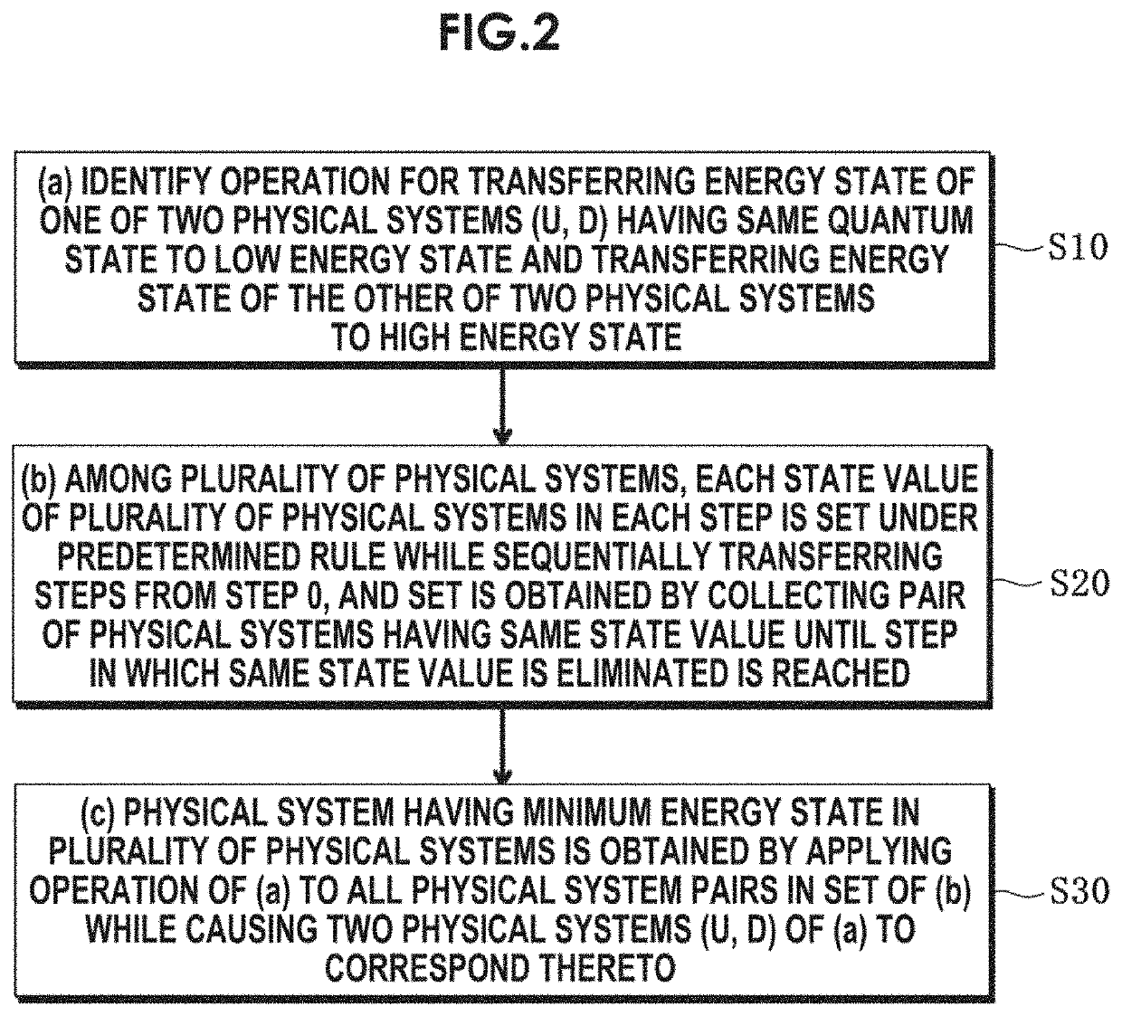
A method for performing quantum annealing computation for solving a discrete optimization problem includes the steps of: (a) identifying an operation for transferring an energy state of one of two physical systems (u, d) having the same quantum state to a low energy state and transferring an energy state of the other of the two physical systems to a high energy state; (b) constructing a network structure among a plurality of physical systems that indicates an order of application of the operation of the step (a) on two physical systems among the plurality of physical systems; and (c) obtaining a physical system having a minimum energy state in the plurality of physical systems by applying the operation of the step (a) to the plurality of physical systems according to the order indicated in the network structure of step (b).

Description

BACKGROUND OF THE INVENTIONField of the Invention[0001]The present invention relates to a method for quantum annealing computation, and more particularly, to a method for performing quantum annealing computation to solve a discrete optimization problem using a quantum annealing computer.Description of the Related Art[0002]A quantum annealing computer is known as a quantum computer that solves a discrete optimization problem using a quantum effect. The quantum annealing computer is a computer for solving a problem (hereinafter referred to as a “discrete optimization problem”) of obtaining a combination of discrete variables that minimizes an objective function (corresponding to optimization), which frequently appears in operation research or the like.[0003]A physical system is designed in which a discrete variable is a physical state and a value of an objective function with respect to the discrete variable becomes the energy of the state. That is, energy is a function of the state. ...

Claims


Application Information

Patent Timeline
IPC IPC(8): G06N10/00
CPCG06N10/00H10N60/10
Inventor IMAFUKU, KENTARO
Owner NAT INST OF ADVANCED IND SCI & TECH
Learn More