Semiconductor integrated circuit capable of autonomously adjusting output impedance

Active Publication Date: 2008-05-08
RENESAS ELECTRONICS CORP
View PDF4 Cites 8 Cited by
  • Summary
  • Abstract
  • Description
  • Claims
  • Application Information

AI Technical Summary

Benefits of technology

[0017]Thus, according to the present invention, it is possible to suppress the number of terminals that should be formed on the package of the semiconductor integrated circuit configured to be capable of autonomously adjusting output impedance.

Problems solved by technology

Accordingly, there is a problem in that the number of terminals that should be provided in the integrated circuit package increases.

Method used


Image

  • Semiconductor integrated circuit capable of autonomously adjusting output impedance
  • Semiconductor integrated circuit capable of autonomously adjusting output impedance
  • Semiconductor integrated circuit capable of autonomously adjusting output impedance

Examples


first embodiment

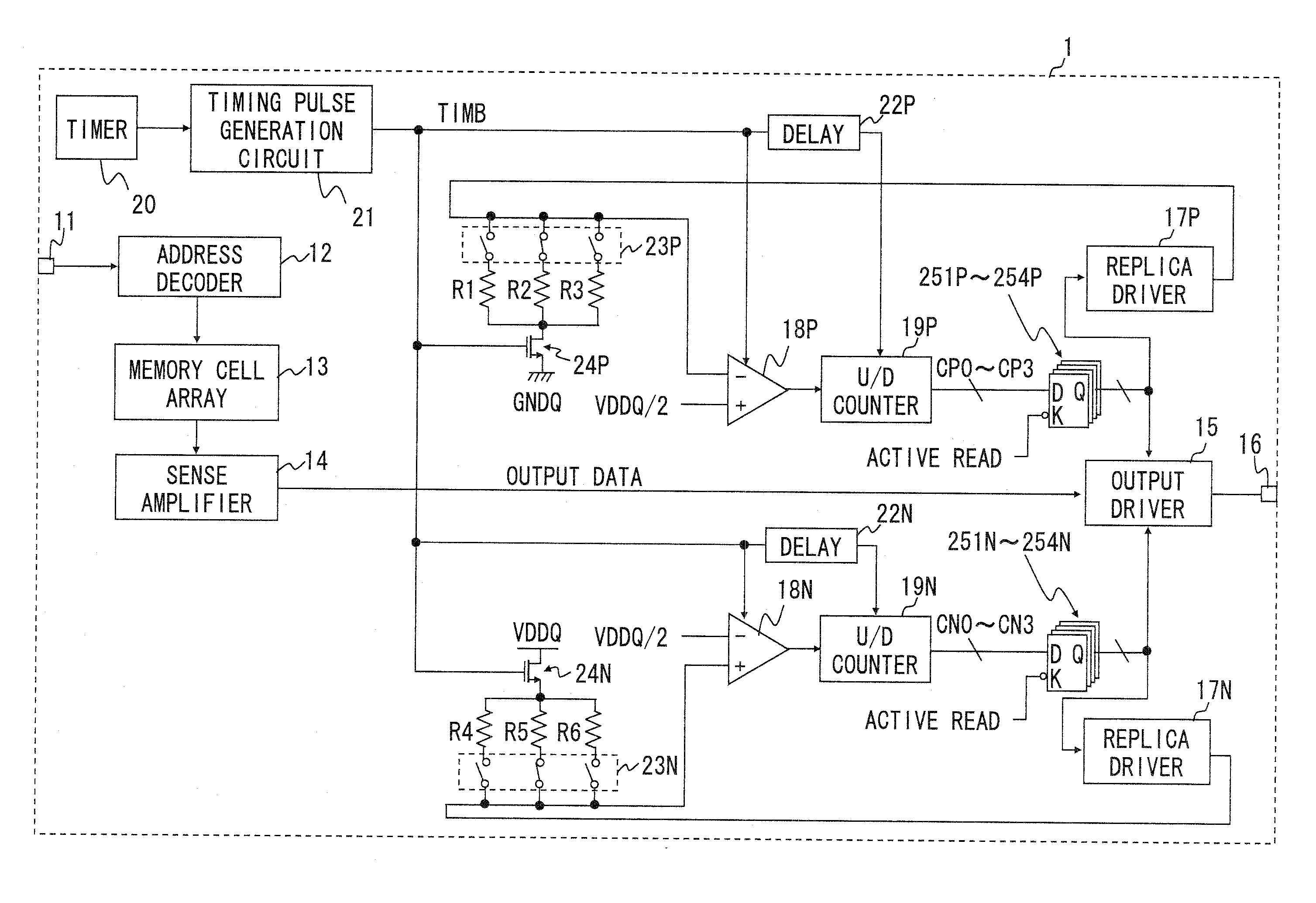
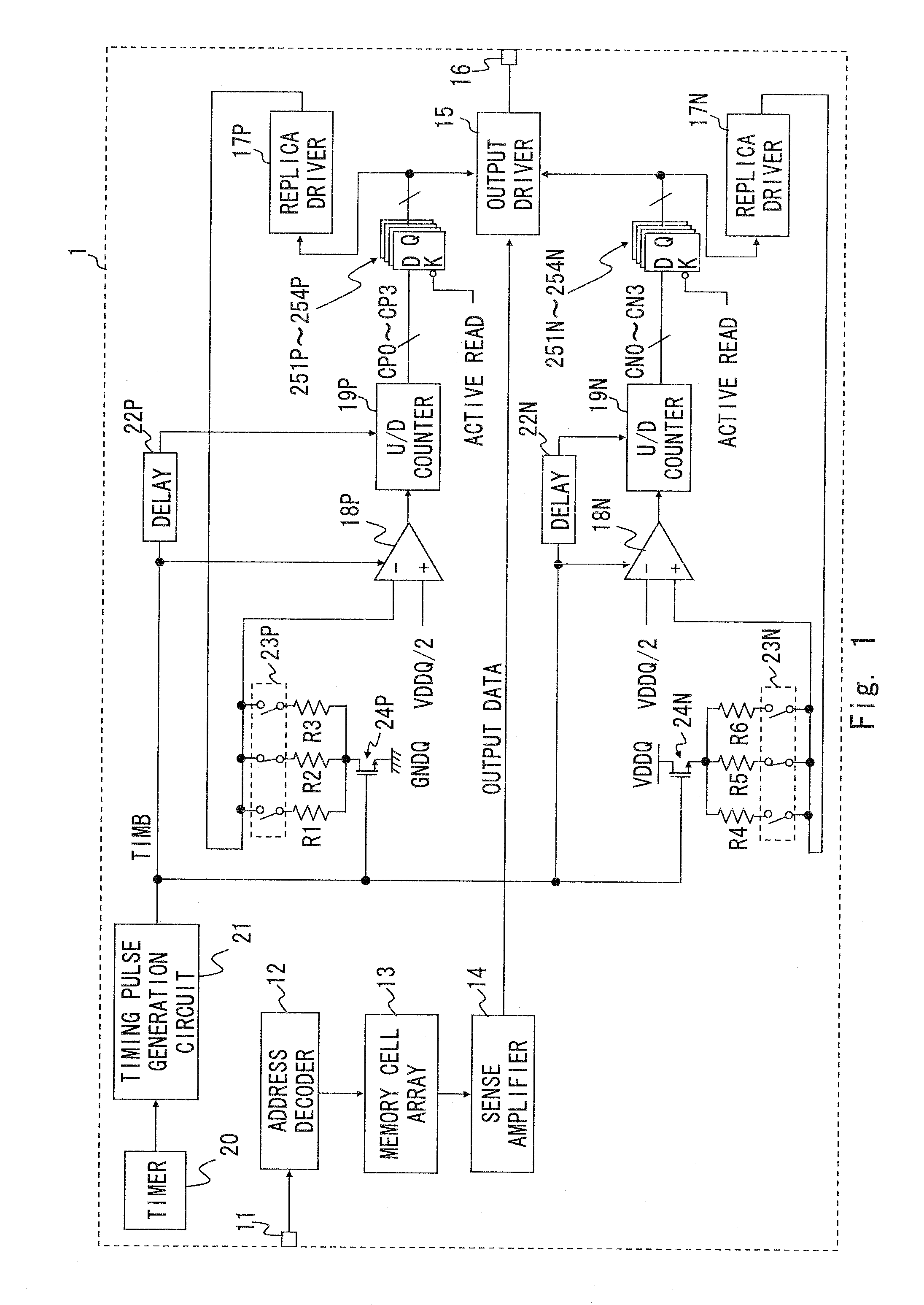
[0027]This Embodiment describes the case of applying the present invention to a DRAM chip. FIG. 1 shows a configuration of the main part of the DRAM chip 1 according to the present Embodiment. In FIG. 1, an address input terminal 11, an address decoder 12, a memory cell array 13, a sense amplifier 14, an output driver 15, a data output terminal 16, replica drivers 17P and 17N, comparators 18P and 18N, and U / D counters 19P and 19N are the same as the configuration components included in a DRAM chip 7 shown in FIG. 6.

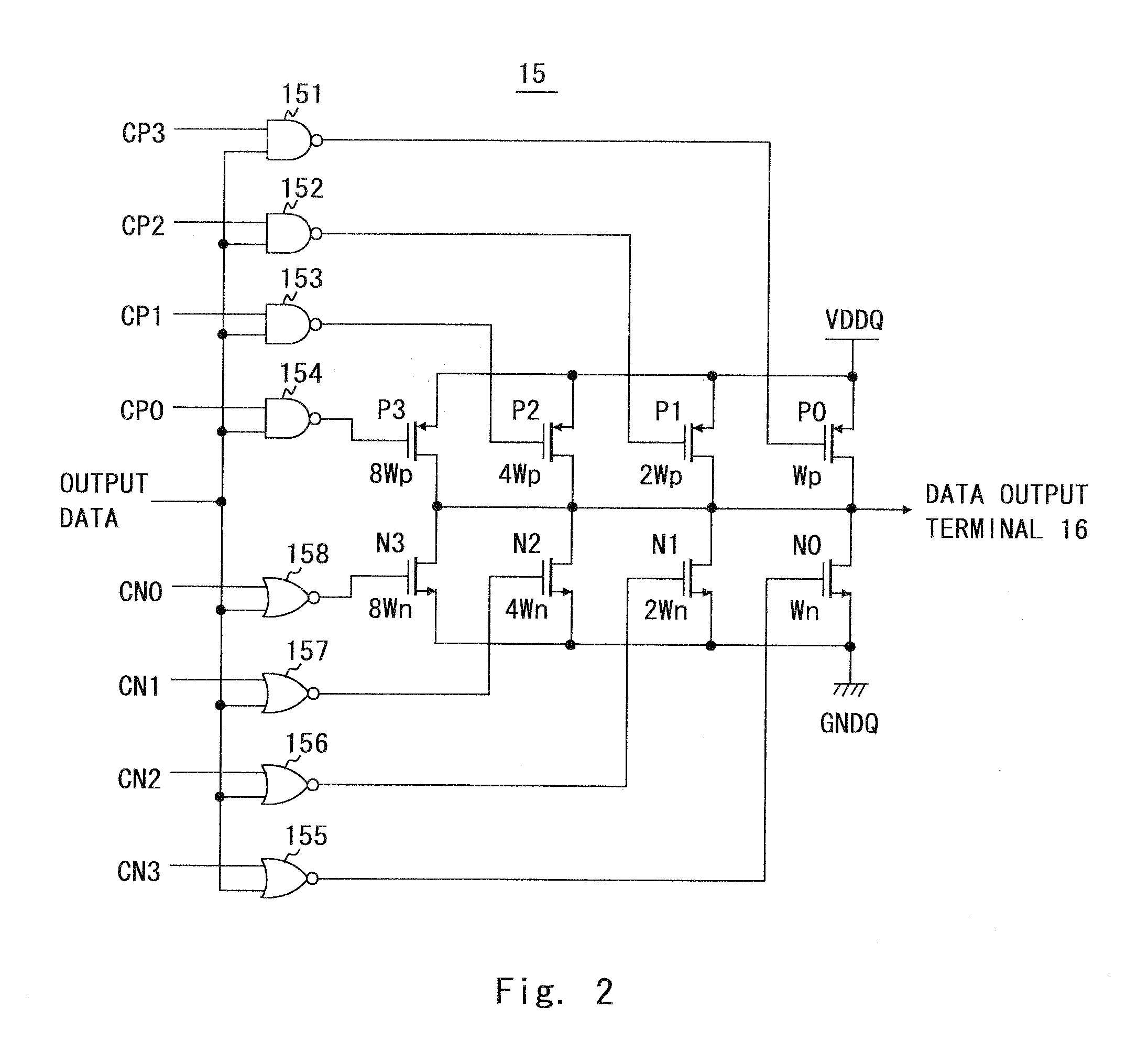
[0028]Now, an example of the configuration of the output driver 15 is shown in FIG. 2, and examples of the replica drivers 17P and 17N are shown in FIGS. 3A and 3B. In the present Embodiment, the U / D counters 19P and 19N are 4-bit counters. In other words, 4-bit values CP0 to CP3 held in the U / D counter 19P are transmitted to the pull-up side circuit of the output driver 15 and the replica driver 17P, as control signals for adjusting the current driving capability. Simila...

second embodiment

[0054]The configuration of a DRAM chip 2 according to the present Embodiment is shown in FIG. 5. The DRAM chip 2 has a configuration made by leaving out the replica driver 17N, the comparator 18N, the delay circuit 22N, the switch group 23N, the transistor switch 24N, and the replica resistors R4 to R6 from the configuration of the DRAM chip 1 according to the first embodiment. The DRAM chip 2 performs an adjustment of the current driving capability at the pull-down side of the output driver 15 by using a comparison result of the comparator 18P at the pull-up side. If the ratio between the current driving capability of the pull-up side transistors P0 to P3 and the current driving capability of the pull-down side transistors N0 to N3 of the output driver 15 is already known, it is possible to perform an output impedance adjustment including the pull-down side circuit of the output driver 15 by applying the configuration shown in FIG. 5. By virtue of the configuration described above,...


PUM


Abstract

A semiconductor integrated circuit includes an output driver, a replica driver, a replica resistor, and an impedance adjustment circuit. The output driver is configured to be capable of changing current driving capability. The replica driver is configured to be capable of changing current driving capability. The replica resistor is connected to an output of the replica driver. The impedance adjustment circuit is configured to adjust the current driving capability of the output driver and the replica driver, based on an output voltage of the replica driver. In addition, the output driver, the replica driver, the replica resistor, and the impedance adjustment circuit are mounted in an integrated circuit package.

Description

BACKGROUND OF THE INVENTION[0001]1. Field of the Invention[0002]The present invention relates to a semiconductor integrated circuit configured to be capable of autonomously adjusting output impedance.[0003]2. Description of Related Art[0004]When a semiconductor integrated circuit transfers data to the outside, if there exists a mismatch between the output impedance of the output driver of the semiconductor integrated circuit and the impedance of a transmission line connected to the output driver, there occurs reflection of a data signal outputted from the output driver. Generally, impedance of a transmission line has a tendency to hardly vary, but output impedance of a semiconductor integrated circuit has a tendency to easily vary according to a fluctuation of the operating voltage or temperature in the circuit. For this reason, there has been contrived an impedance adjustment circuit that can detect a fluctuation of the impedance and autonomously correct it.[0005]The impedance adju...

Claims


Application Information

Patent Timeline
IPC IPC(8): H03K19/0175
CPCH03K19/0005
Inventor FUKUSHI, TETSUO
Owner RENESAS ELECTRONICS CORP
Why Eureka
Try Eureka