
Multi-position sprayer component for spraying implements

a sprayer and multi-position technology, applied in the direction of spray nozzles, botany apparatus and processes, horticulture, etc., can solve the problems of large size and configuration of the nozzle body, and the relative heavyness of the solenoid valv

Active Publication Date: 2019-06-06
WILGER INDS
View PDF1 Cites 3 Cited by
  • Summary
  • Abstract
  • Description
  • Claims
  • Application Information

AI Technical Summary

Benefits of technology

The nozzle apparatus in this patent makes it easier to position components like solenoid valves in a way that avoids damage.

Problems solved by technology

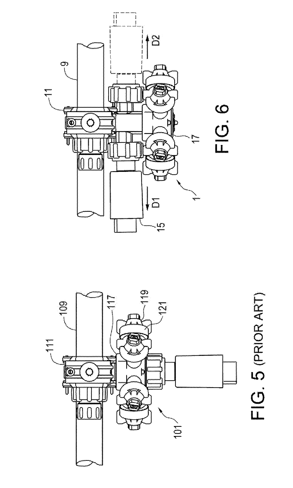
The nozzle bodies themselves are generally of molded plastic and are very light weight however the solenoid valves are relatively heavy as they contain metal coils, plungers and the like.
Often the solenoid valves will extend a relatively significant distance out from the nozzle body, placing torque on the nozzle body which can lead to damage in rough field conditions.
The size and configuration of the nozzle bodies can be problematic when arranging the bodies on the boom as care must be taken to ensure the nozzle bodies do not contact any part of the apparatus when folding the booms between the operating position and the transport position.

Method used


Image

  • Multi-position sprayer component for spraying implements
  • Multi-position sprayer component for spraying implements
  • Multi-position sprayer component for spraying implements

Examples


Embodiment Construction

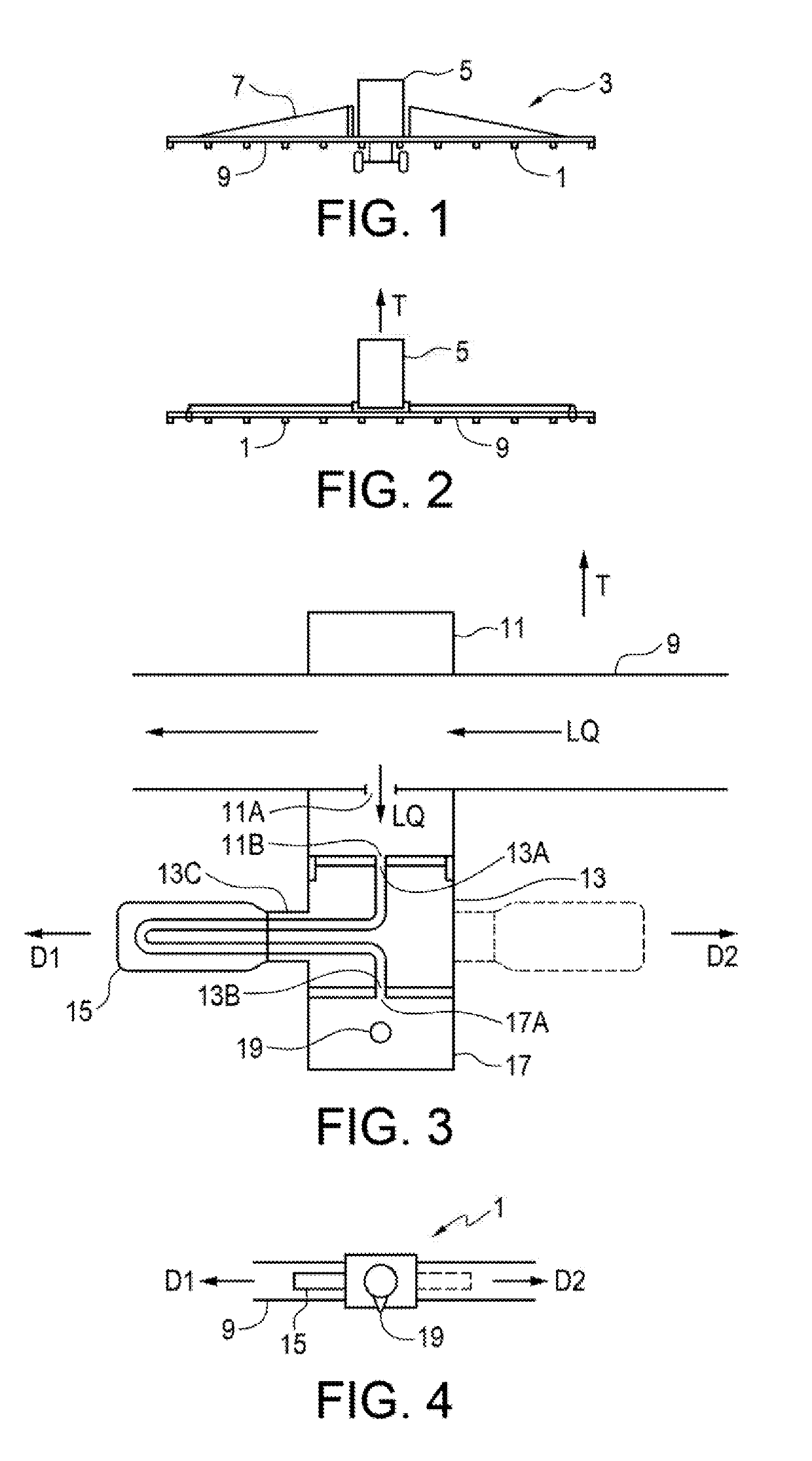
[0022]FIG. 1 illustrates an embodiment of a nozzle apparatus 1 of the present disclosure. As schematically illustrated in FIGS. 1 and 2, the nozzle apparatus 1 is typically mounted on a sprayer boom assembly 3 extending laterally from a spray vehicle 5 configured to move in an operating travel direction T. The sprayer boom assembly 3 typically comprises a boom structure 7 and a liquid conduit 9 mounted along the boom structure 7. The nozzle apparatuses 1 are spaced along the spray boom assembly 3 and connected to the liquid conduit

[0023]The nozzle apparatus 1 comprises, as schematically illustrated in FIG. 3, a conduit mounting member 11 comprising a conduit input 11A adapted to be connected to the liquid conduit 9 such that liquid LQ passing through the liquid conduit 9 flows into the conduit input 11A and out through a conduit output 11B of the conduit mounting member 11.

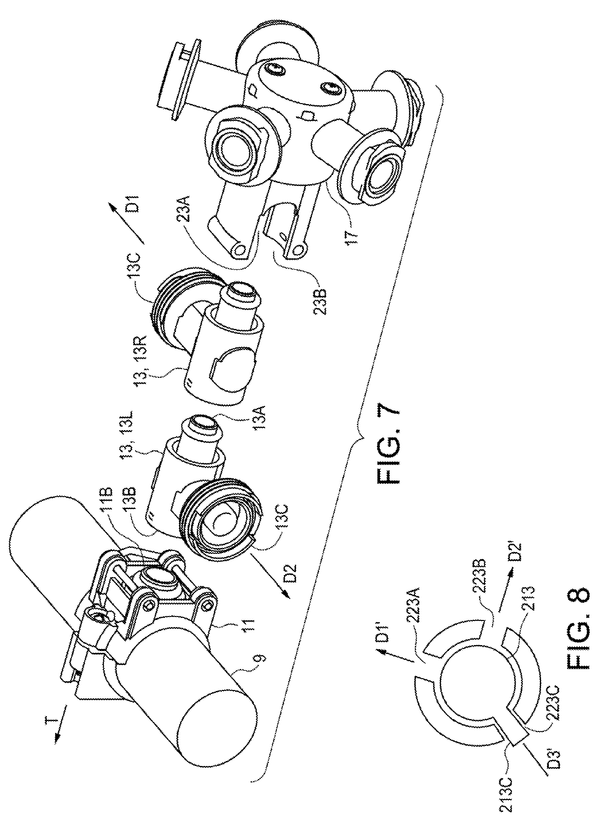
[0024]A component mounting member 13 comprises a component input 13A releasably connected to the conduit output...


PUM


Abstract

A nozzle body apparatus having a conduit mounting member with a conduit input adapted to be connected such that liquid passing through a liquid conduit flows into the conduit input and out through a conduit output. A component mounting member has a component input releasably connected to the conduit output, a component attachment element, and a component output. Liquid passing out the conduit output flows into the component input then through a sprayer component connected to the component attachment element to the component output and then to a nozzle. The component mounting member is connectable to the conduit output in a first orientation where the component attachment element extends from the conduit output in a first direction, and is connectable to the conduit output in a second orientation where the component attachment element extends from the conduit output in a second different direction that is different from the first direction.

Description

FIELD OF THE INVENTION[0001]This disclosure relates to the field of spraying equipment and in particular nozzle body assemblies for spraying equipment.BACKGROUND[0002]Implements for spraying liquid chemicals on fields, roads and the like typically include a liquid container, a laterally extending liquid conduit mounted on a boom with nozzle bodies connected to the liquid conduit at a desired spacing, and a pump operative to draw liquid from the container and to direct pressurized liquid through the conduit to nozzle\s mounted in the nozzle bodies.[0003]In agricultural operations such chemicals include herbicides, pesticides, fungicides, fertilizers, and the like, and each field may be sprayed several times to apply the various chemicals needed during a growing season and between growing seasons. Thus it is desirable to provide spraying implements with very wide coverage and laterally extending booms of 120 feet or more in length.[0004]It is also necessary to move such spraying imple...

Claims


Application Information

Patent Timeline
IPC IPC(8): A01G25/09B05B12/16
CPCA01G25/09B05B12/16B05B1/1645B05B1/3053B05B15/658B05B15/14A01M7/00
Inventor WILGER, WILFRED H.
Owner WILGER INDS
Learn More