
System and Method for Adaptive Braking

a technology of adaptive braking and system, applied in the direction of braking systems, locomotives, braking components, etc., can solve the problems of significant in-train forces and reaction time of air brake systems, and achieve the effects of improving efficiency, accuracy and economic benefits, and reducing human intervention

Inactive Publication Date: 2019-06-06
WESTINGHOUSE AIR BRAKE TECH CORP
View PDF19 Cites 9 Cited by
  • Summary
  • Abstract
  • Description
  • Claims
  • Application Information

AI Technical Summary

Benefits of technology

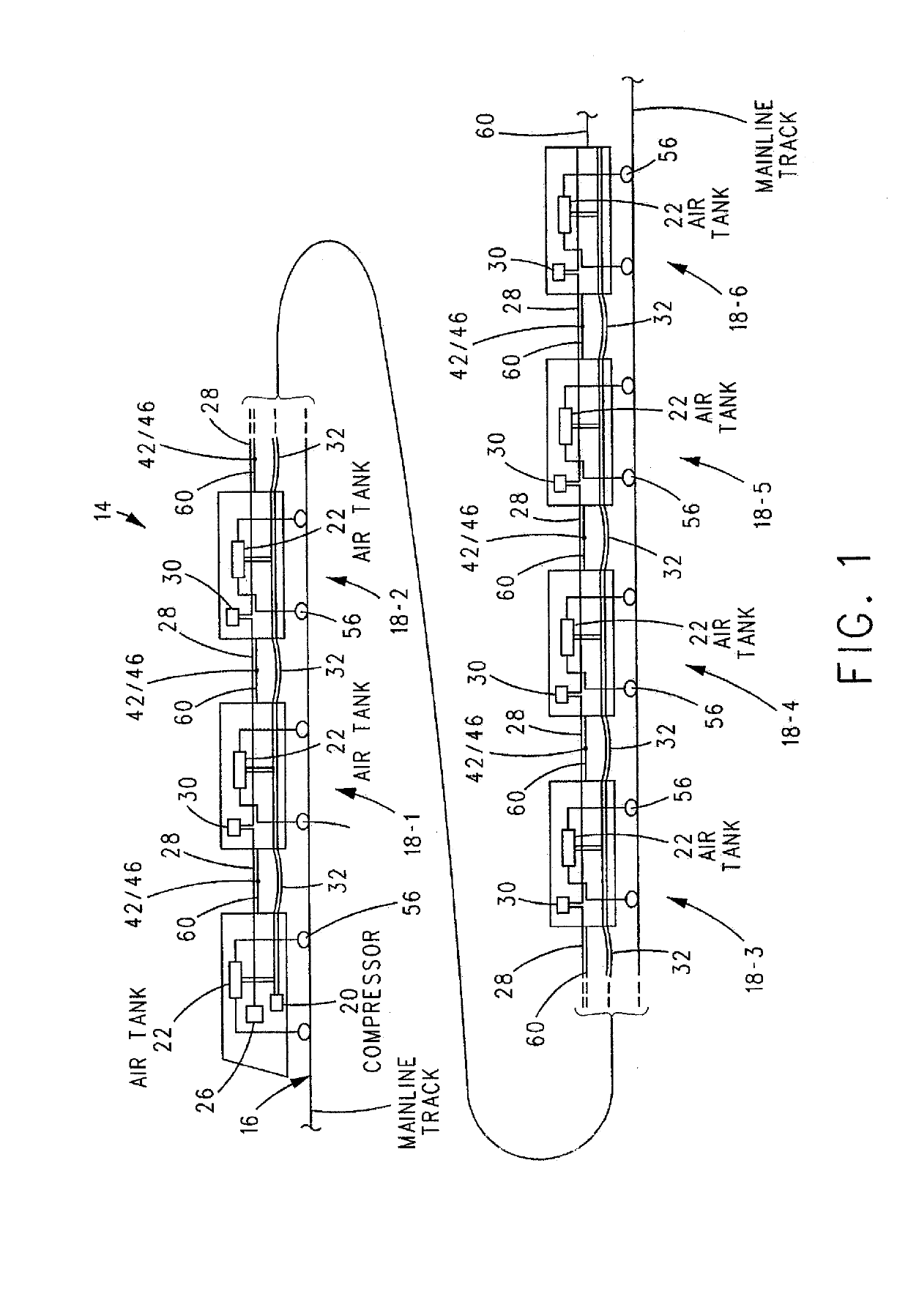
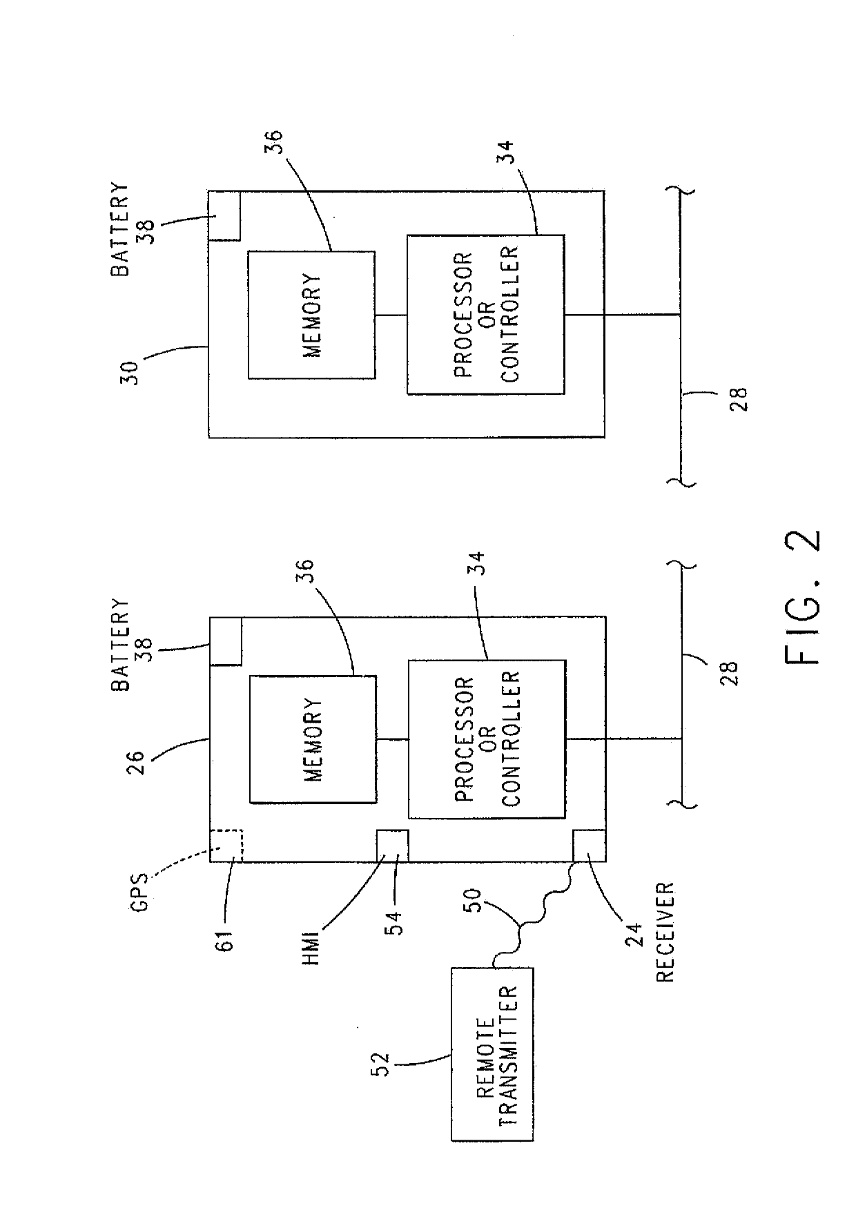
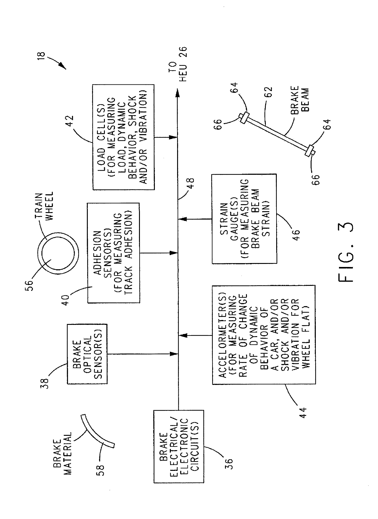
This patent explains a system and method for braking multiple cars on a train based on their condition, cargo, speed, and other factors that affect braking effectiveness. It also mentions the popularity of a type of braking called rotation-based EEH, which can be used in a train environment or the Internet of Things. This technology has the potential to improve efficiency, accuracy, and economic benefit by integrating physical objects with computer-based systems. Ultimately, the patent aims to provide a more advanced and adaptive braking system for rail cars.

Problems solved by technology

One of the drawbacks of such air brake systems is reaction time.
This uneven braking can cause significant in-train forces to build up between the rail cars in a train.

Method used


Image

  • System and Method for Adaptive Braking
  • System and Method for Adaptive Braking
  • System and Method for Adaptive Braking

Examples


Embodiment Construction

[0109]For the purposes of the following detailed description, it is to be understood that the invention may assume various alternative variations and step sequences, except where expressly specified to the contrary. It is also to be understood that the specific devices and methods described in the following specification are simply exemplary embodiments, examples, or aspects of the invention. Moreover, other than in any operating examples, or where otherwise indicated, all numbers expressing, in preferred and non-limiting embodiments, examples, or aspects, quantities of ingredients used in the specification and claims are to be understood as being modified in all instances by the term “about”. Accordingly, unless indicated to the contrary, the numerical parameters set forth in the following specification and attached claims are approximations that may vary depending upon the desired properties to be obtained by the present invention. At the very least, and not as an attempt to limit...


PUM


Abstract

In a method of braking a number of rail cars of a train travelling on a mainline track, in response to a unique braking command provided to each rail car of a first subset of rail cars, wherein each braking command includes a level or percentage of braking the brakes of the rail car are to assume, the brakes of the rail car are set to level or percentage of braking included in the unique braking command provided to the rail car. Thereafter, in response to a unique braking command provided to each rail car of a second, different subset of rail cars, the brakes of the rail car are set to level or percentage of braking included in the unique braking command provided to the rail car.

Description

BACKGROUND OF THE INVENTIONField of the Invention[0001]The present invention relates to a method of controlling a train equipped with an electronically controlled pneumatic (ECP) braking system,Description of Related Art[0002]A traditional train braking system uses pneumatic valves to control and generate brake applications on the rail cars along the length of the train, which train, in an example, can include a locomotive and one, or two, or more rail cars. In general, this traditional system includes a brake pipe that runs the entire length of the train and which supplies air from an air compressor located the locomotive to air reservoirs mounted on each of the rail cars and the locomotive. When it is desired to apply the brakes of the train, one or more manually operated brake control valves in the locomotive are adjusted by an operator thereby causing a reduction in the brake pipe air pressure. As the brake pipe pressure reduces, the brake service portion on each rail car divert...

Claims


Application Information

Patent Timeline
Patent Type & Authority Applications(United States)
IPC IPC(8): B60T13/66B60T17/22B61C17/12B60T13/36
CPCB60T13/665B60T17/228B61C17/12B60T13/365B60T2270/84B61H13/00B61H15/00
Inventor VENKATASUBRAMANIAN, SATHYA VAGHEESWARWILSON, M. FRANK
Owner WESTINGHOUSE AIR BRAKE TECH CORP
Learn More