
Airborne Wind Profiling Portable Radar System and Method

a portable radar and airborne wind technology, applied in the field of airborne wind profiling portable radar system and method, can solve the problems of inability to effectively use an airborne platform to determine vector wind, lack of height coverage much above the boundary layer, and higher cost of building and operating 404-mhz profilers

Active Publication Date: 2019-06-06
FOSTER-MILLER
View PDF0 Cites 17 Cited by
  • Summary
  • Abstract
  • Description
  • Claims
  • Application Information

AI Technical Summary

Benefits of technology

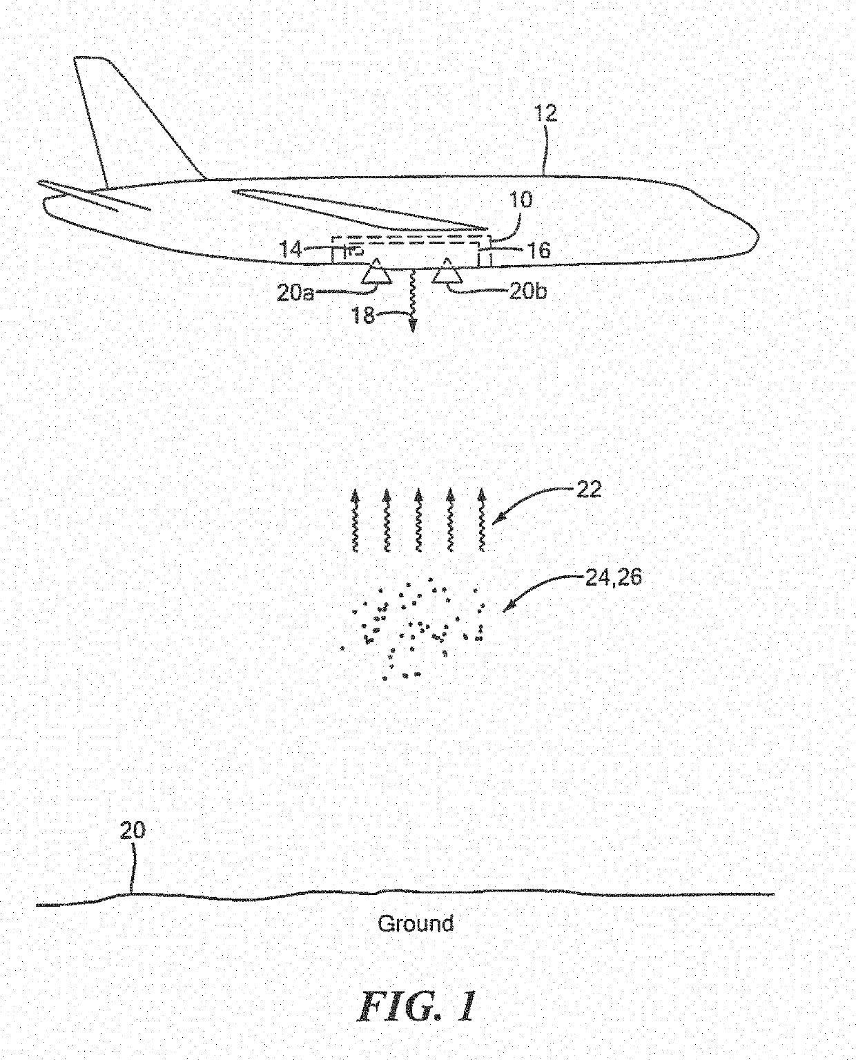
The patent describes an airborne wind profiling system that uses a mobile platform with a radar and an inertial measurement unit (IMU) to measure the position and orientation of the platform. The system is designed to continuously receive navigation data and radar signals from the platform and the ground, and to process the data to determine the position of each reflected target. The system can also adjust the pointing angle of the radar to optimize the detection of wind direction and velocity. The technical effects of this system include improved wind profiling accuracy and efficiency, as well as improved safety and reliability for airborne wind profiling applications.

Problems solved by technology

The 404-MHz profilers are more expensive to build and operate, but they provide the deepest coverage of the atmosphere.
The 915-MHz profilers are smaller and cheaper to build and operate, but they lack height coverage much above the boundary layer.
However, the conventional wind profilers discussed above are ground based systems have large apertures (antenna diameters), large range cells (vertical resolution), large blanking ranges (height coverage) and slow response (temporal resolution) and, therefore, cannot be used effectively in an airborne platform to determine vector wind velocity as a function of altitude above the ground

Method used


Image

  • Airborne Wind Profiling Portable Radar System and Method
  • Airborne Wind Profiling Portable Radar System and Method
  • Airborne Wind Profiling Portable Radar System and Method

Examples


Embodiment Construction

[0064]Aside from the preferred embodiment or embodiments disclosed below, this invention is capable of other embodiments and of being practiced or being carried out in various ways. Thus, it is to be understood that the invention is not limited in its application to the details of construction and the arrangements of components set forth in the following description or illustrated in the drawings. If only one embodiment is described herein, the claims hereof are not to be limited to that embodiment. Moreover, the claims hereof are not to be read restrictively unless there is clear and convincing evidence manifesting a certain exclusion, restriction, or disclaimer.

[0065]There are several problems associated with conventional wind profiling systems. First, mounting a ground based radar to a moving platform that is operating at velocities much greater than the wind speed requires new data processing as disclosed herein since the targets now smear in velocity space, and the velocity of ...


PUM


Abstract

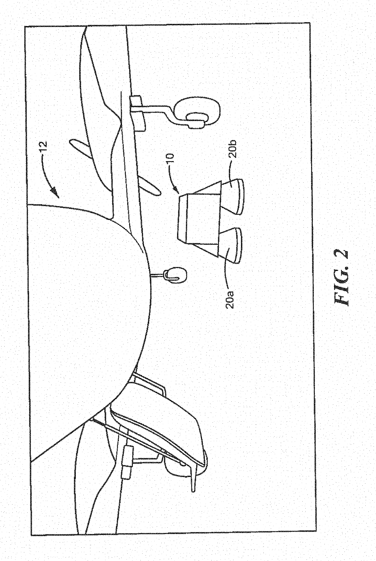
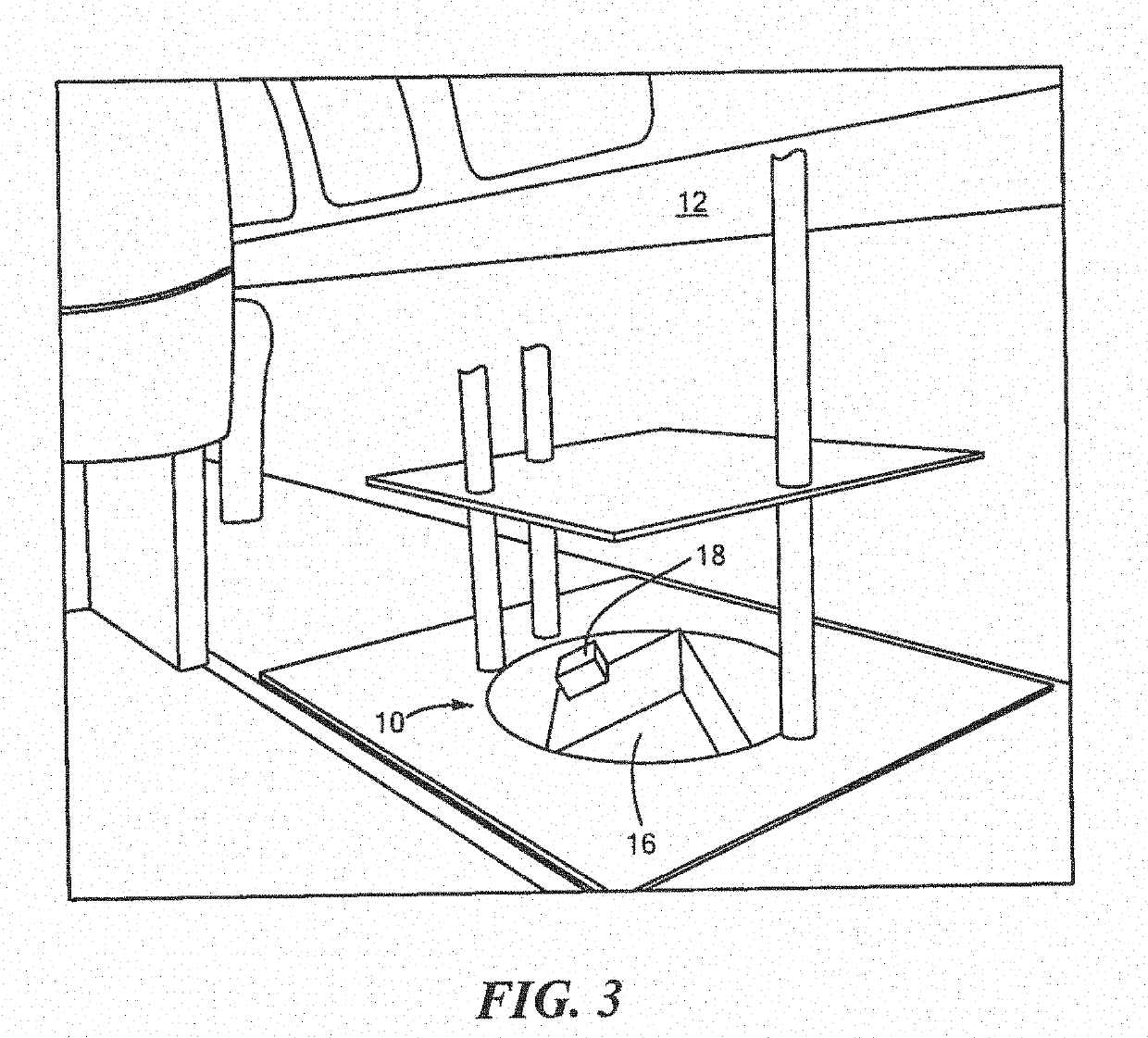
An airborne wind profiling portable radar (AWiPPR) system comprising a mobile airborne platform including one or more navigation units configured to produce navigation data including at least the position and orientation of the mobile airborne platform. A radar unit is mounted and positioned to the mobile airborne platform, the radar unit is configured to transmit a wide-band frequency modulated continuous wave radar signal in a downward direction from the mobile airborne platform towards the ground and configured to continuously receive a reflected signal from a plurality of clear air scatters (CAS) targets or volumetric targets and output radar data. An inertial measurement unit (IMU) in communication with the one or more navigation units and the radar unit is configured to receive the navigation data and determine the position and orientation of the radar at a specific point in time and output IMU data. A data acquisition unit in communication with the radar unit and the is configured to receive and time align radar data and the IMU data for each reflected signal from each of the plurality of CAS targets or volumetric targets to provide an antenna pointing direction for each received reflected signal. The data acquisition unit is configured to process the time aligned radar data and IMU data to determine a distance and a Doppler velocity of each of the plurality of CAS targets or volumetric targets, provide a range, a velocity, and an antenna pointing direction for each of the plurality of CAS targets or volumetric targets, and calculate a vector wind velocity using the range, the velocity, and the antenna pointing direction for each of the plurality of CAS targets or volumetric scatters targets, The data acquisition unit may be configured to further correct the range, the velocity, and / or the antenna pointing direction of each of the plurality of CAS targets or volumetric targets to accommodate for a motion shift in data produced by one or more on a relative motion and orientation of the mobile airborne platform, a Doppler spread in the range, the velocity and / or the antenna pointing direction, and a ground echo.

Description

RELATED APPLICATIONS[0001]This application claims benefit of and priority to U.S. Provisional Application Ser. No. 62 / 589,650 tiled Nov. 22, 2017, under 35 U.S.C. §§ 119, 120, 363, 365, and 37 C.F.R. § 1.55 and § 1.78, which is incorporated herein by this reference.FIELD OF THE INVENTION[0002]This subject invention relates to an airborne wind profiling portable radar system and method.BACKGROUND OF THE INVENTION[0003]Wind profilers are Doppler radars that typically operate in the VHF (30-300 MHz) or UHF (300-1000 MHz) frequency bands. There are three primary types of radar wind profilers in operation in the U.S. today. The NOAA Profiler Network (NPN) profiler operates at a frequency of 404 MHz. The second type of profiler that is used by NOAA research and outside agencies is the 915-MHz boundary-layer profiler. The 404-MHz profilers are more expensive to build and operate, but they provide the deepest coverage of the atmosphere. The 915-MHz profilers are smaller and cheaper to build...

Claims


Application Information

Patent Timeline
Patent Type & Authority Applications(United States)
IPC IPC(8): G01S13/95G01C21/16G01S7/40G01S13/58G01S13/86
CPCG01S13/953G01C21/165G01S7/40G01S13/584G01S13/589G01S13/86Y02A90/10G01C21/1652G01W1/02
Inventor HENDERSON, MARKBRADLEY, MARSHALL
Owner FOSTER-MILLER
Learn More