Luminous keyboard

Active Publication Date: 2019-06-06
PRIMAX ELECTRONICS LTD
View PDF0 Cites 3 Cited by
  • Summary
  • Abstract
  • Description
  • Claims
  • Application Information

AI Technical Summary

Benefits of technology

The present invention provides a luminous keyboard that creates a uniform glow. The keyboard includes a switch circuit board, a supporting plate, a backlight module, and at least one ring-shaped structure. The ring-shaped structure is made of fluorescent or light diffusion material and is placed under the key structure. The light beams generated by the backlight module are reflected by the ring-shaped structure and provide a consistent illumination on the keycaps. The luminous keyboard of the invention provides an enhanced and consistent illumination.

Problems solved by technology

However, since the supporting plate openings 221 are uniformly distributed in the supporting plate 22, the light beams B cannot be uniformly outputted.

Method used


Image

  • Luminous keyboard
  • Luminous keyboard
  • Luminous keyboard

Examples


Embodiment Construction

[0020]For overcoming the drawbacks of the conventional technology, the present invention provides a luminous keyboard.

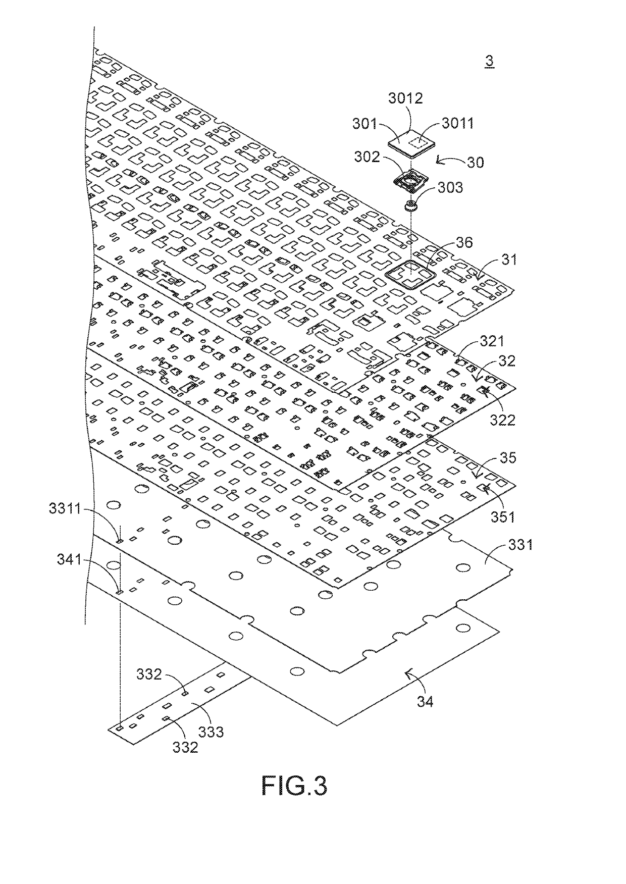
[0021]The structure of the luminous keyboard will be described with reference to FIGS. 3 and 4. FIG. 3 is a schematic exploded view illustrating a portion of a luminous keyboard according to an embodiment of the present invention. FIG. 4 is a schematic cross-sectional view illustrating a portion of the luminous keyboard according to the embodiment of the present invention. The luminous keyboard 3 comprises plural key structures 30, a switch circuit board 31, a supporting plate 32, a backlight module 33, a reflecting plate 34, a light-shading plate 35 and plural ring-shaped structures 36. The plural key structures 30 are exposed outside the luminous keyboard 3. The switch circuit board 31 is located under the plural key structures 30. When the switch circuit board 31 is triggered by one of the plural key structures 30, a corresponding key signal is generated. The supp...


PUM


Abstract

A luminous keyboard includes plural key structures, a switch circuit board, a supporting plate, a backlight module and plural ring-shaped structures. The switch circuit board is located under the keycaps of the key structures. The supporting plate is located under the switch circuit board and connected with the key structures. The backlight module is located under the supporting plate. The backlight module generates a light beam. The plural ring-shaped structure are disposed on the switch circuit board and arranged around the corresponding key structures. When the light beam is reflected by the key structures, the light beam is received by the plural ring-shaped structure. Due to the material properties of the ring-shaped structures, the periphery regions of the keycaps generate a uniform luminous effect.

Description

FIELD OF THE INVENTION[0001]The present invention relates to a keyboard, and more particularly to a luminous keyboard with an illuminating function.BACKGROUND OF THE INVENTION[0002]Generally, the widely-used peripheral input device of a computer system includes for example a mouse device, a keyboard, a trackball device, or the like. Via the keyboard, characters and symbols can be directly inputted into the computer system. As a consequence, most users and most manufacturers of input devices pay much attention to the development of keyboards.[0003]FIG. 1 is a schematic top view illustrating the outer appearance of a conventional keyboard. As shown in FIG. 1, there are plural keys 10 on a surface of the conventional keyboard 1. These keys 10 are classified into several types, e.g. ordinary keys 101, numeric keys 102 and function keys 103. When one of these keys 10 is depressed by the user's finger, a corresponding signal is issued to the computer, and thus the computer executes a func...

Claims


Application Information

Patent Timeline
IPC IPC(8): G06F3/02H01H13/83H01H13/704H03K17/967
CPCG06F3/0202H01H13/83H01H13/704H03K17/967H01H2219/036H01H2219/052H01H2219/056H01H2219/06H01H2219/062G06F3/0238
Inventor LIN, YU-MING
Owner PRIMAX ELECTRONICS LTD
Why Eureka
Try Eureka