Device and method for cooling living tissue

a technology of living tissue and cooling device, which is applied in the field of devices and methods for cooling living tissues, can solve the problems of increasing the time required for patient preparation by several fold, increasing the pain and psychological stress of ivt, and increasing the level of anesthesia, so as to achieve rapid and safe delivery of cryoanesthesia or cryoanalgesia

Inactive Publication Date: 2019-06-13
RECENSMEDICAL INC
View PDF0 Cites 17 Cited by
  • Summary
  • Abstract
  • Description
  • Claims
  • Application Information

AI Technical Summary

Benefits of technology

[0007]The present disclosure or teaching is contemplated to solve the problem in the conventional art. Thus, an object of the present disclosure is to provide a device and a method for delivering cryoanesthesia or cryoanalgesia rapidly and safely.

Problems solved by technology

IVT is a painful and psychologically stressful procedure, and patients often demand maximal anesthesia before an injection.
These methods require several minutes for the onset of maximal anesthesia, increasing the time required for patient preparation by several fold.
While the method of eye drops of topical anesthetics is the most time-efficient method, the level of anesthesia is moderate and patients often complain of injection pain.
In addition to the possible side effects, chemical anesthesia agents often result in adverse effects when applied to the eye surface such as eye dryness and soreness, which further lead to patient discomfort.
The rapidly increasing number of IVTs has resulted in severe strain in ophthalmic clinic work flow and long patient waiting time, forcing retina specialists to sacrifice patient experience for managing their busy clinics.

Method used


Image

  • Device and method for cooling living tissue
  • Device and method for cooling living tissue
  • Device and method for cooling living tissue

Examples


Embodiment Construction

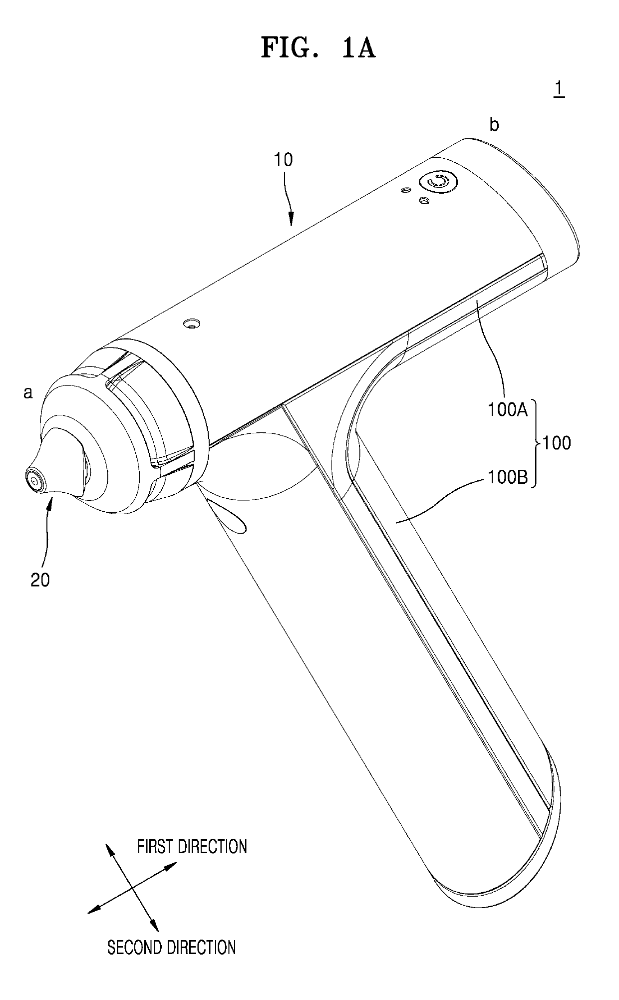
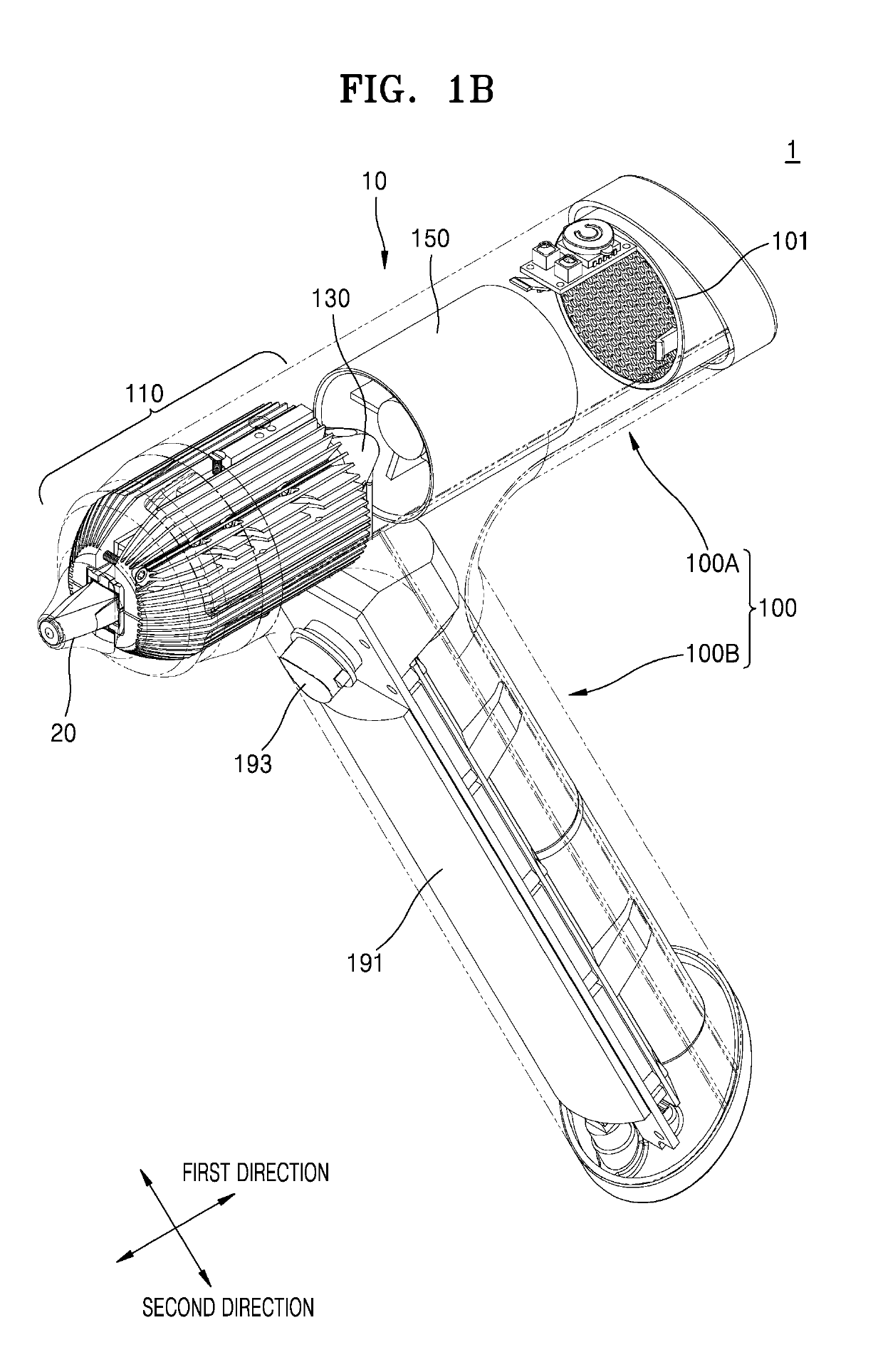
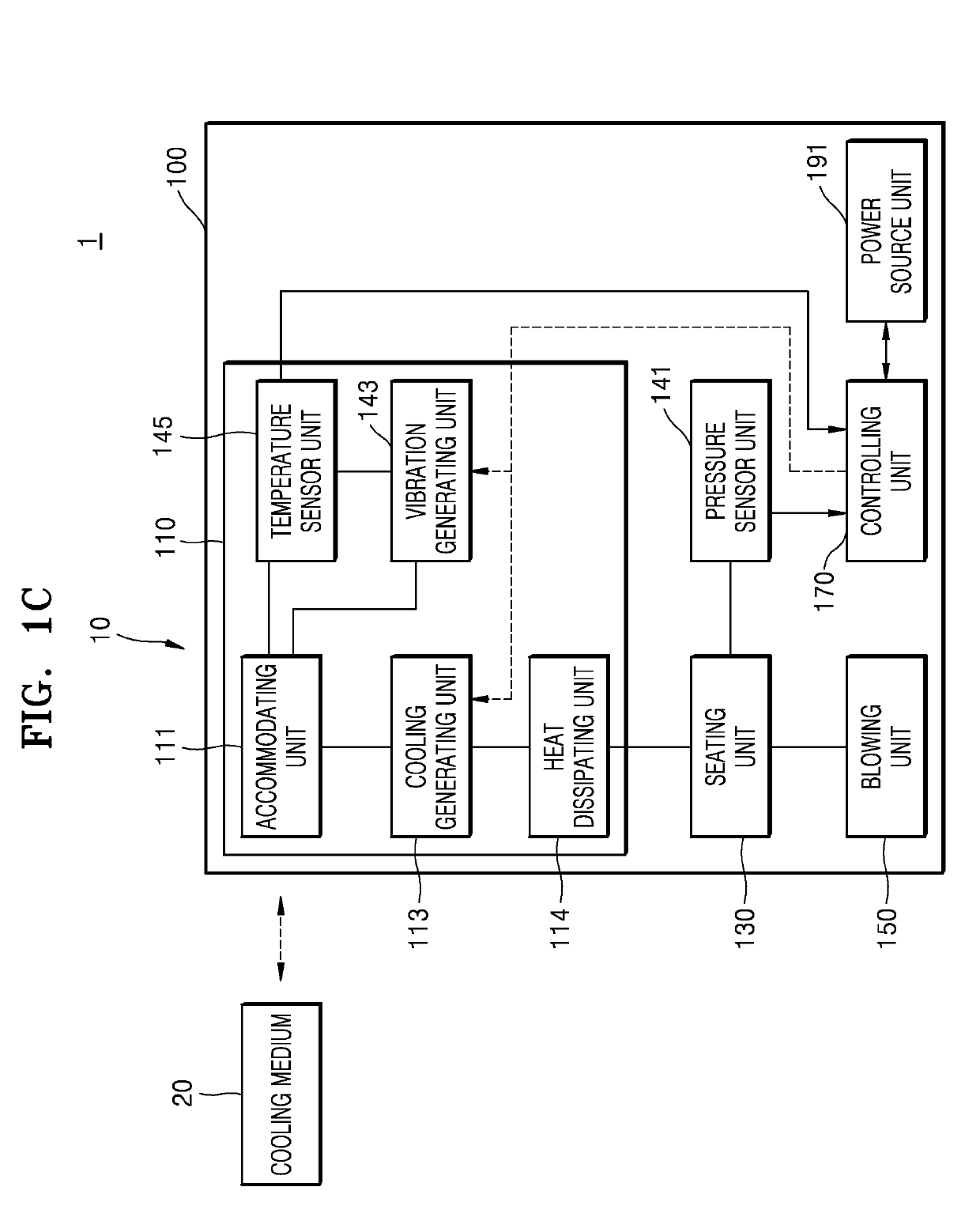
[0031]Description will now be given in detail according to examples disclosed herein, with reference to the accompanying drawings. For the sake of brief description with reference to the drawings, the same or equivalent components may be provided with the same reference numbers, and description thereof will not be repeated. In general, a term such as “module” and “unit” may be used to refer to elements or components. Use of such a term herein is merely intended to facilitate description of the specification, and the term itself is not intended to give any special meaning or function. In the present disclosure, that which is well-known to one of ordinary skill in the relevant art has generally been omitted for the sake of brevity. The accompanying drawings are used to help easily understand various technical features and it should be understood that the examples presented herein are not limited by the accompanying drawings. As such, the present disclosure should be construed to exten...


PUM


Abstract

The present disclosure provides a device and a method for cooling living tissues for a medical purpose and other purposes. The cooling device comprises: a container configured to accommodate a cooling medium, the container including a plurality of divided members each having a contact surface which is thermally coupled with the cooling medium; a cooling generator configured to provide cooling energy to the container, and disposed on another surface of the divided member other than the contact surface; and a lubricating member provided to the contact surface of the divided member, wherein the container is configured to be thermally coupled with the cooling medium via the lubricating member.

Description

CROSS-REFERENCE TO RELATED APPLICATIONS[0001]This application claims the benefit under 35 U.S.C. § 120 and § 365(c) to a prior PCT International Application No. PCT / KR2018 / 006169, filed on May 30, 2018, which claims the benefits of U.S. Provisional Patent Application No. 62 / 512,189, filed on May 30, 2017, U.S. Provisional Patent Application No. 62 / 534,206, filed on Jul. 19, 2017, U.S. Provisional Patent Application No. 62 / 565,095, filed on Sep. 29, 2017, Korean Patent Application No. 10-2017-0184439, filed on Dec. 29, 2017, Korean Patent Application No. 10-2017-0184440, filed on Dec. 29, 2017, Korean Patent Application No. 10-2017-0184441, filed on Dec. 29, 2017, Korean Patent Application No. 10-2017-0184442, filed on Dec. 29, 2017, Korean Patent Application No. 10-2017-0184443, filed on Dec. 29, 2017, Korean Patent Application No. 10-2017-0184444, filed on Dec. 29, 2017, Korean Patent Application No. 10-2017-0184445, filed on Dec. 29, 2017, Korean Patent Application No. 10-2017-018...

Claims


Application Information

Patent Timeline
Patent Type & Authority Applications(United States)
IPC IPC(8): A61F7/12A61B18/02
CPCA61F7/12A61B18/02A61F2007/0056A61B2018/00452A61B2018/00011A61F2007/0087A61B18/20A61F2007/126A61M5/422A61F2007/0052A61F2007/0075A61F2007/0261A61M5/44A61F2007/0285A61F2007/0086A61F2007/0096A61F2007/0004A61F7/007A61F9/007A61M19/00A61B18/0218A61F2007/0093
Inventor KIM, GUN-HO
Owner RECENSMEDICAL INC
Why Eureka
Try Eureka